
Marine Fire Insulation: Materials & Standards (SOLAS)
Marine fire insulation keeps A-class and H-120 divisions within SOLAS/IMO limits. Rock wool is the workhorse; ceramic fiber covers hot uptakes. Material + class map.
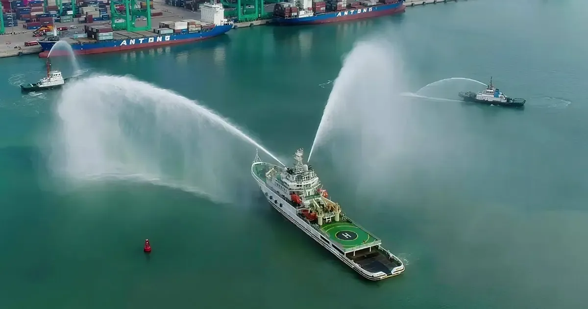
Marine fire insulation keeps a ship's A-class divisions, engine-room boundaries, and exhaust uptakes within SOLAS/IMO temperature limits during a fire. The workhorse material is rock wool — A1 non-combustible, dimensionally stable, and a decent acoustic absorber. Ceramic fiber steps in where exhaust or uptakes run hot, and calcium silicate board adds a rigid backup layer on load-bearing boundaries. Getting the specification right means understanding three things at once: what the SOLAS class actually measures, which materials can carry it, and how much thickness and density each position on the vessel needs.
What SOLAS / IMO Demand
A-class bulkheads and decks must limit the temperature rise on the unexposed side to 139 °C above ambient, with no point exceeding 180 °C, during the standard fire test. That is a thermal-duty spec, not just "non-combustible."
The Standard Fire Test Curve Behind Every Marine Fire Rating
Every marine fire insulation duty — A-15, A-30 or A-60 — is measured against the IMO standard time-temperature curve, and that curve is far more aggressive than first-time specifiers expect. Furnace temperature climbs steeply in the opening minutes, then flattens out:
| Time from ignition | Internal furnace temperature |
|---|---|
| Start | 20 °C (initial furnace temperature) |
| 5 minutes | 576 °C |
| 10 minutes | 679 °C |
| 15 minutes | 738 °C |
| 30 minutes | 841 °C |
| 60 minutes | 945 °C |
The practical consequence: most of the temperature jump happens in the first five minutes. An insulation that survives 900 °C steady-state can still fail an A-60 test if heat crosses it fast enough during that opening ramp, because the assembly is judged on what happens on its unexposed face minute by minute — not on whether it survives the peak.
Test geometry is fixed as well. The bulkhead or deck specimen presents an exposed area of not less than 4.65 m², with a height (or deck length) of 2.44 m, built to resemble the actual construction and including at least one joint. That joint is there on purpose: it is where real divisions fail.
A-Class Divisions: A-15, A-30, A-60 and H-120
SOLAS classifies fire divisions by how long they contain a standard fire. The class number is the minutes the division holds both integrity (no flame or gas passage) and insulation (temperature-rise limits).
| Class | Smoke & flame integrity | Temperature rise held for | Max single-point rise (unexposed face) | Typical location |
|---|---|---|---|---|
| A-0 | 60 minutes | Not required | No limit | Control stations, stairway boundaries with low fire load |
| A-15 | 60 minutes | 15 minutes | 180 °C | Light-risk bulkheads, some corridor boundaries |
| A-30 | 60 minutes | 30 minutes | 180 °C | Accommodation-to-service boundaries |
| A-60 | 60 minutes | 60 minutes | 180 °C | Engine-room boundaries, stairway enclosures, galleys |
| H-60 / H-120 | 60 / 120 minutes | 60 / 120 minutes | 180 °C | Offshore modules and high-speed craft |
Read that table carefully, because one point is misread constantly: the number in the class is not how long the division holds back flames. Every A-class division resists smoke and flame for a full 60 minutes. The number is the thermal duty — how long the unexposed face stays inside the 139 °C average / 180 °C single-point limits. That is why an A-0 division still has to be built from steel or an equivalent material, and why A-60 cannot be met simply by making a boundary thicker at random.
The temperature limits themselves apply to the unexposed side measured above the original temperature: an average rise of no more than 139 °C (rounded to 140 °C in several references) across the face, and no more than 180 °C at any single point including any joint.
B-Class and C-Class Divisions: What Changes Outside A-Class
Not every fire boundary on a vessel is A-class. Accommodation linings, ceilings and internal doors mostly fall into B-class, and C-class appears where only non-combustibility matters.
| Aspect | A-class | B-class | C-class |
|---|---|---|---|
| Construction | Steel or equivalent material | Recognised non-combustible materials | Approved non-combustible materials |
| Flame integrity | Prevent smoke and flame for 60 minutes | Prevent flame for 30 minutes | No requirement |
| Max average temperature rise | 139 °C above original | 139 °C above original | No limit |
| Max single-point rise | 180 °C above original | 225 °C above original | No limit |
| Classes available | A-0, A-15, A-30, A-60 | B-0, B-15 | n/a |
| Typical use | Engine rooms, machinery spaces, stairways, galleys | Cabin linings, corridor and public-space boundaries | Minor internal partitions, joinery cores |
Two details drive material selection here. First, B-class permits a higher single-point limit (225 °C against 180 °C), because a B-class division is not protecting against a fully developed machinery-space fire. Second, A-, B- and C-class profiles must all be built from non-combustible material — defined in the IMO Fire Test Procedures (FTP) Code as a material that neither burns nor gives off flammable vapours in sufficient quantity for self-ignition when heated to approximately 750 °C.
That 750 °C threshold explains why lightweight organic-bonded or foamed products generally cannot serve as the core of a marine fire insulation assembly, no matter how well they perform in architectural fire tests.
Which Division Class Goes Where: Ship Space Matrix
Marine fire insulation specs start from SOLAS, which assigns a required class to every boundary according to the fire risk of the spaces on both sides. The pattern below reflects the standard requirement set for accommodation and service layouts; the vessel's approved fire control plan always governs on a specific ship.
| Boundary between | Typical required class |
|---|---|
| Machinery space ↔ accommodation, corridor, stairway or control station | A-60 |
| Galley ↔ accommodation space | A-60 |
| Galley ↔ corridor | A-30 |
| Control station ↔ stairway or corridor | A-0 |
| Control station ↔ accommodation space | A-60 |
| Stairway ↔ accommodation space | A-0 |
| Corridor ↔ cabin | B-15 |
| Cabin ↔ cabin | B-15 to C-class (non-combustible) |
| Machinery space ↔ machinery space | A-0 where risk is equal, A-60 where separation is required |
| Pump room ↔ accommodation or machinery space | A-60 |
| Cargo hold ↔ accommodation or machinery space | A-60 on gas and chemical carriers; A-0 to A-30 for dry cargo |
Read the logic rather than memorising the cells. Boundaries around a machinery space, a galley, or any space with both a high fire load and ignition sources are A-60. Boundaries between two similar low-risk accommodation spaces step down to B-class. Everything else sits between those two poles, which is why the same ship will carry four different division classes within a few metres of structure.
H-120 Marine Insulation
H-120 is the 120-minute fire-resistance class required on offshore modules, high-speed craft, and installations where evacuation takes longer than one hour. It is a stricter thermal duty than A-60: the same 139 °C / 180 °C temperature-rise limits, but held for two hours instead of one.
In practice, H-120 divisions use higher-density rock wool board or ceramic fiber — typically thicker, installed over a steel substrate with certified cladding — sized so the unexposed face stays within limits for the full 120 minutes. If you are specifying H-120, request the approved product test certificate (IMO FTP Code Part 3) rather than relying on catalog ratings.
Marine Fire Insulation Thickness and Density by Ship Space
Once the class is fixed, marine fire insulation thickness and density follow from the duty. The figures below are typical starting points for budgeting and space planning on new builds and refits — the type-approved certificate for the chosen system sets the final numbers.
| Ship location | Typical class | Insulation form | Typical thickness | Typical density |
|---|---|---|---|---|
| Engine-room bulkhead | A-60 | Rock wool board | 80–100 mm | 150–180 kg/m³ |
| Engine casing / funnel casing | A-60 to A-30 | Rock wool board with cladding | 60–100 mm | 120–150 kg/m³ |
| Exhaust uptake and silencer casing | Hot-side layer | Ceramic fiber blanket | 25–50 mm | 128–160 kg/m³ |
| Galley boundary | A-60 | Rock wool board | 80–100 mm | 150–180 kg/m³ |
| Stairway enclosure | A-60 to A-0 | Rock wool board | 0–100 mm | 100–150 kg/m³ |
| Accommodation ceiling and bulkhead lining | B-15 | Rock wool board | 40–50 mm | 120–150 kg/m³ |
| Corridor lining | B-15 | Rock wool board | 40–50 mm | 100–120 kg/m³ |
| Steel deck carrying load | A-60 | Calcium silicate backup plus rock wool | 30–50 mm each | 220–1000 kg/m³ (calcium silicate) |
| Pipe and cable penetration | Same as parent division | Certified penetration seal | Per approval | Per approval |
Two things stand out in that table. First, an A-60 duty takes roughly twice the thickness in an engine room as it does in accommodation, because the same temperature-rise limit has to hold four times longer against a much hotter neighbouring space. Second, the exhaust uptake is the one row where ceramic fiber replaces rock wool, because metal temperatures on the gas side routinely run past what a 650 °C-rated stone wool product can hold continuously.
Weight Trade-offs: Density Costs Money Afloat
Marine fire insulation mass matters more at sea than ashore. Every kilogram above the waterline affects stability, draught and fuel burn, so a single fire class often has two or three defensible solutions at different densities.
| Build-up | Approximate mass per m² | When it earns its weight |
|---|---|---|
| 50 mm rock wool at 120 kg/m³ | ~6 kg/m² | B-15 accommodation linings with short fire duty |
| 100 mm rock wool at 150 kg/m³ | ~15 kg/m² | A-60 boundaries that also need to block machinery noise |
| 50 mm ceramic fiber at 128 kg/m³ | ~6.4 kg/m² | Exhaust uptakes above continuous stone wool limits |
| 25 mm calcium silicate at 250 kg/m³ | ~6.3 kg/m² | Load-bearing backup where compression resistance dominates |
Optimising downward only works if the type-approved system allows it. Going below the tested thickness is never permitted — the saving has to come from choosing a form that meets the identical duty with less mass, not from trimming the build that was actually tested.
Marine Fire Insulation Material Comparison
Five materials carry almost every marine fire insulation duty. The right choice is a function of three things: the division class you must meet, the continuous service temperature the position actually sees, and whether the boundary has to carry load.
| Material | Continuous service | Division reach | Typical density | Where it wins |
|---|---|---|---|---|
| Rock wool blanket | ~650 °C | A-15 → A-60 | 60–150 kg/m³ | Default A-class divisions; fire plus acoustic |
| Rock wool board | ~650 °C | A-30 → H-120 | 100–200 kg/m³ | Rigid bulkheads, decks, H-class boundaries |
| Ceramic fiber blanket | 1000–1260 °C | H-60 / H-120 hot side | 96–160 kg/m³ | Exhaust uptakes, incinerator casings, penetrations |
| Calcium silicate board | 900–1050 °C | A-60 backup, H-class | 220–1000 kg/m³ | Load-bearing backup on steel boundaries |
| Glass wool | 250–350 °C | B / C-class only | 12–48 kg/m³ | Accommodation acoustics, HVAC, low fire duty |
Two things decide most of these calls. First, temperature: glass wool is an acoustic material, not a fire-division material, and it is only admissible where the division duty is low. Second, rigidity: calcium silicate is chosen not for its conductivity but because it holds shape under compression on a steel boundary where rock wool would slowly compact.
Thickness by Division Class
Thickness is not a free variable. For a certified division the build is fixed by the approved system — insulation type, density, thickness, cladding and fixing method all together. The figures below are typical starting points for budgeting and space planning, not a substitute for the certificate.
| Division | Typical build | Common locations |
|---|---|---|
| B-15 / C-class | 25–50 mm glass or rock wool | Accommodation internal partitions |
| A-15 | 40–60 mm rock wool (~80 kg/m³) | Light-risk bulkheads, corridor boundaries |
| A-30 | 60–80 mm rock wool (~100 kg/m³) | Accommodation-to-service boundaries |
| A-60 | 75–100 mm rock wool (~120 kg/m³) | Engine-room boundaries, stairway enclosures |
| H-60 | 100 mm+ high-density rock wool or ceramic fiber | Offshore module steel, high-speed craft |
| H-120 | 120–150 mm+ certified system | Offshore modules with long evacuation times |
Note how the step from A-60 to H-120 is not simply "twice the time, twice the thickness." It changes the material: H-class duties usually move to higher-density rock wool board or add a ceramic fiber hot-side layer, because the same 139 °C / 180 °C temperature-rise limit has to hold for two hours instead of one.
Fire-Resistant Marine Materials
The materials accepted for marine fire divisions share three properties: A1 non-combustibility, low smoke and toxicity per the IMO FTP Code, and a continuous service temperature above the duty:
- Rock wool blanket and board — the default for A-class divisions and accommodation boundaries. A1, service to about 650 °C continuous, naturally water-repellent, good for both fire and noise. See rock wool blanket and rock wool board.
- Ceramic fiber blanket — for hot spots: exhaust uptakes, incinerator casings, and high-temperature penetrations where rock wool would break down. Continuous use to 1000–1260 °C. See ceramic fiber blanket.
- Calcium silicate board — the rigid, load-bearing backup on steel boundaries. A1, dimensionally stable, holds its shape under compression. See calcium silicate insulation board.
- Glass wool — lightweight acoustic insulation for accommodation and HVAC areas where the fire duty is lower (B/C-class divisions).
Each of these families is covered in more depth in its own material hub: rock wool insulation, ceramic fiber insulation, calcium silicate insulation and glass wool insulation.
Beyond Fire Resistance: Smoke, Toxicity and Surface Flammability
Fire resistance attracts most of the attention, but a marine fire insulation product has to clear several other tests before it is admissible on a vessel. The IMO FTP Code separates them deliberately:
- Part 1 — non-combustibility. The material must neither burn nor give off flammable vapours in sufficient quantity for self-ignition when heated to approximately 750 °C. Without this result the material cannot form part of an A-, B- or C-class division at all.
- Part 2 — smoke and toxicity. The smoke released during combustion is measured for optical density and toxic gas concentration. On a ship, incapacitation from smoke inhalation is a larger casualty mechanism than heat, and escape routes pass through the same compartments.
- Part 5 — surface flammability. Exposed surfaces must demonstrate low flame spread, so a fire in a corridor does not propagate along the lining itself.
- Part 3 — fire resistance of divisions. The assembly-level test that produces the A-15 / A-30 / A-60 or B-15 duty.
The practical trap is this: a product can hold a valid Part 3 certificate for a concealed engine-room bulkhead and still be inadmissible as a corridor lining, because corridor applications additionally require Part 2 and Part 5 results. When reviewing a datasheet, check all four parts rather than only Part 3. Our A1 non-combustible insulation guide covers how European classifications relate to these marine requirements.
Marine vs Offshore: Two Different Rulebooks
One clarification that saves confusion on mixed projects. This guide covers shipboard fire insulation under SOLAS — A-class bulkheads, decks and accommodation boundaries on vessels, where the duty is defined by SOLAS Chapter II-2 and tested to the IMO FTP Code.
Offshore platforms work to a different framework. Module boundaries are rated H-60 / H-120 and are sized against hydrocarbon fire curves (ISO 834) and, where a high-pressure release is credible, jet fire (UL 1709) — with the thickness driven by the steel section factor as much as by the fire duration. That is passive fire protection engineering rather than shipboard insulation, and it is covered separately in our offshore fireproofing guide.
If your project is an FPSO or a floating unit, you may well need both: SOLAS A-class divisions in the accommodation block, and H-class PFP on the process modules.
Where It Goes
Marine fire insulation appears in five positions on almost every vessel: engine-room and machinery-space boundaries (A-60 down to A-15), exhaust uptakes and silencer casings (ceramic fiber territory), accommodation ceilings and corridor linings where fire duty and noise control overlap, pipe and duct penetrations through fire divisions, and offshore module boundaries rated H-60 or H-120.
Penetrations, Joints and Fixings: Where Divisions Actually Fail
Marine fire insulation only performs as part of a certified division, and installed systems fail at discontinuities far more often than through the insulation layer itself. Three details consistently decide whether the installed division behaves like the tested specimen:
- Penetration seals must match the parent division. A pipe passing through an A-60 bulkhead requires an A-60-rated seal, tested for the same pipe material, diameter and contents. Substituting an unrated sleeve is among the most common survey findings.
- Joints carry their own duty. The standard test specimen deliberately includes at least one joint, because that is where gap gauges find openings. Panel fixing centres belong to the certificate, not to installer judgement.
- Fixings have to survive the fire. Pins, washers and hangers form part of the tested construction. Non-rated fixings soften well before 60 minutes and let insulation slump away from the substrate, exposing bare steel to the furnace.
How to Write a Marine Fire Insulation Specification
"A-60 rock wool" is a product description, not a marine fire insulation specification, and it will not survive plan review. A defensible line item names five things:
- The class and location — A-60 engine-room bulkhead, frames 40 to 52, port side.
- The product and its form — rock wool board rather than blanket; nominal density 150 kg/m³.
- The thickness and compression limit — 100 mm single layer, compressed no more than the approved percentage at fixing points.
- The cladding or facing — sheet material and thickness exactly as tested.
- The fixing method and centres — pin type, washer size, spacing, plus the type-approval certificate number the assembly belongs to.
Close the item with the certificate reference and the approval body recognised by the vessel's flag state. If any one of the five changes during construction, treat it as a re-approval rather than a substitution.
Practical Notes
- Pair insulation with certified cladding or jacketing rated for the division.
- Watch compression: over-compressed rock wool loses R-value and can open fire paths.
- On hot uptakes, ceramic fiber modules outperform blanket for vibration and thermal cycling.
- Verify the IMO FTP Code certificate for the exact product and thickness; the classification society audits the installed system, not the catalog spec.
- On A-60 boundaries specifically, work from a full heat-balance rather than a catalog thickness — our A-60 marine insulation guide walks through the calculation.
IMO FTP Code Part 3: What the Certificate Actually Covers
This is the part that causes the most expensive rework. An A-60 certificate is issued for an approved system, not for a material.
The IMO FTP Code Part 3 fire test qualifies a complete assembly: the insulation product, its density, its thickness, the cladding or facing, the fixing method and spacing, and the supporting steel. Change any one of those and the certificate no longer applies — even if the insulation itself is unchanged.
In practice that means:
- A catalog "A-60 rating" is a claim about one tested configuration, not a property of the product.
- Substituting a different density of the same rock wool product usually invalidates the approval.
- The certificate is audited by the classification society against the installed system, not against the datasheet.
When you specify, ask for the certificate for the exact product, density, thickness and cladding being installed, and confirm the approval body is recognised by the vessel's flag state. For EU-flagged vessels this normally also means the Marine Equipment Directive wheel mark; US-flagged vessels look for USCG approval.
Five Specification Mistakes We See on Marine Fire Insulation
1. Specifying the material instead of the system. "A-60 rock wool" is not a specification. The certificate defines the assembly — density, thickness, cladding, fixing. Write all four into the spec.
2. Over-compressing the insulation. Rock wool loses thermal performance when compressed beyond its design density, and compression can open gaps that become fire paths. Fixing centres matter as much as the insulation itself.
3. Treating penetrations as an afterthought. Pipes, cables and ducts passing through a fire division are the most common failure point in both testing and service. The penetration seal has to be rated for the same division as the bulkhead it passes through.
4. Mixing densities within one division. A boundary built partly at 80 kg/m³ and partly at 120 kg/m³ has not been tested in either configuration. Consistency is not cosmetic.
5. Substituting cladding to save weight or cost. Cladding is part of the tested system. Swapping a facing without re-testing is one of the fastest ways to fail a class survey.
Acoustic Performance
On most vessels the same insulation is doing two jobs. Accommodation boundaries, corridor ceilings and HVAC runs need fire performance and noise control, and rock wool is usually the material that satisfies both — it is porous enough to absorb sound and dense enough to meet A-class fire duties.
Where acoustics dominate and the fire duty is low (B/C-class), glass wool is lighter and cheaper and performs better per kilogram on absorption. Where fire dominates, rock wool board is the safer call. Ceramic fiber is a poor acoustic material and is not chosen for noise control.
For the thermal and acoustic side of the same question — pipe thickness, condensation control, NRC targets and HVAC zones — see our marine insulation thermal and acoustic specification guide.
Related Reading
- A-60 Marine Insulation: How It Works + Thickness Guide
- Offshore Fireproofing: Passive Fire Protection on Platforms
- Rock Wool Insulation for Marine & Offshore Engineering
- Marine Insulation: Thermal & Acoustic Specifications
- Non-Combustible Insulation Systems: A1 Fire Rating Explained
- What Temperature Can Rock Wool Withstand?
- Marine & Offshore Insulation Applications
- Rock Wool Insulation Hub · Ceramic Fiber Insulation Hub · Calcium Silicate Insulation Hub
For a focused look at engine rooms and machinery spaces, see our Ship Engine Room & Machinery Space A-60 insulation guide.
Explore the full Rosetexwool product range — ceramic fiber, rock wool, calcium silicate, microporous aerogel and glass wool — with specification tables and application notes for each family.
Explore flexible aerogel and microporous insulation options in our aerogel insulation guide.
Frequently asked
What insulation is used for marine fire protection? +
Primarily A1 rock wool for A-class divisions and accommodation; ceramic fiber for hot exhaust uptakes and penetrations where rock wool would break down.
What temperature must marine fire insulation withstand? +
SOLAS/IMO limit the unexposed surface to 139°C above ambient (max 180°C) in the standard fire test — a thermal-duty limit, not just non-combustibility.
Is rock wool allowed on ships? +
Yes. Rock wool is A1 non-combustible and the standard choice for marine A-class divisions; it is also naturally water-repellent, useful in engine rooms.
Rock wool or ceramic fiber for exhaust uptakes? +
Ceramic fiber — uptakes run hot enough to break rock wool down (rock wool caps near 650°C continuous). Ceramic fiber serves 1000–1260°C.
What is H-120 marine insulation? +
H-120 is a 120-minute fire-resistance class required on offshore modules and high-speed craft. It applies the same temperature-rise limits as A-60 (139°C average / 180°C maximum on the unexposed side) but holds them for two hours instead of one, typically with higher-density rock wool or ceramic fiber over a steel substrate.
What materials are fire-resistant for marine use? +
Rock wool (A1) is the workhorse for A-class and H-120 divisions; ceramic fiber covers hot exhaust uptakes to 1260°C; calcium silicate board adds a rigid load-bearing backup; glass wool serves lower-duty acoustic areas. All must meet the IMO FTP Code smoke and toxicity limits.
What does A-0 mean on a ship fire division? +
An A-0 division still resists smoke and flame for a full 60 minutes, but it carries no requirement to limit temperature rise on the unexposed face. It must be built of steel or an equivalent material, and it is used around control stations and stairways where the adjacent spaces have a low fire load. Insulation may be omitted, but the boundary itself remains non-combustible.
How thick is marine fire insulation for an A-60 engine-room bulkhead? +
Typically 80-100 mm of rock wool board at 150-180 kg/m³. The exact figure belongs to the type-approved system rather than to the product: the certificate covers a specific density, thickness, cladding and fixing pattern together, so altering any one of those outside the approved assembly voids the approval.
Does marine fire insulation need more testing than fire resistance? +
Yes. Beyond Part 3 fire resistance of the division, the IMO FTP Code also assesses non-combustibility at approximately 750 °C (Part 1), smoke and toxicity (Part 2), and surface flammability (Part 5). Concealed engine-room boundaries may rely mainly on Part 3, but linings in escape routes and accommodation spaces generally require results from all four parts.
Request a quote
Interested in our insulation solutions? Send us your requirements and our team responds within one business day.