
Offshore Fireproofing: Passive Fire Protection on Platforms
How offshore PFP (passive fire protection) is rated, where it goes on a platform, and what materials actually survive salt, vibration, and jet-fire heat load.
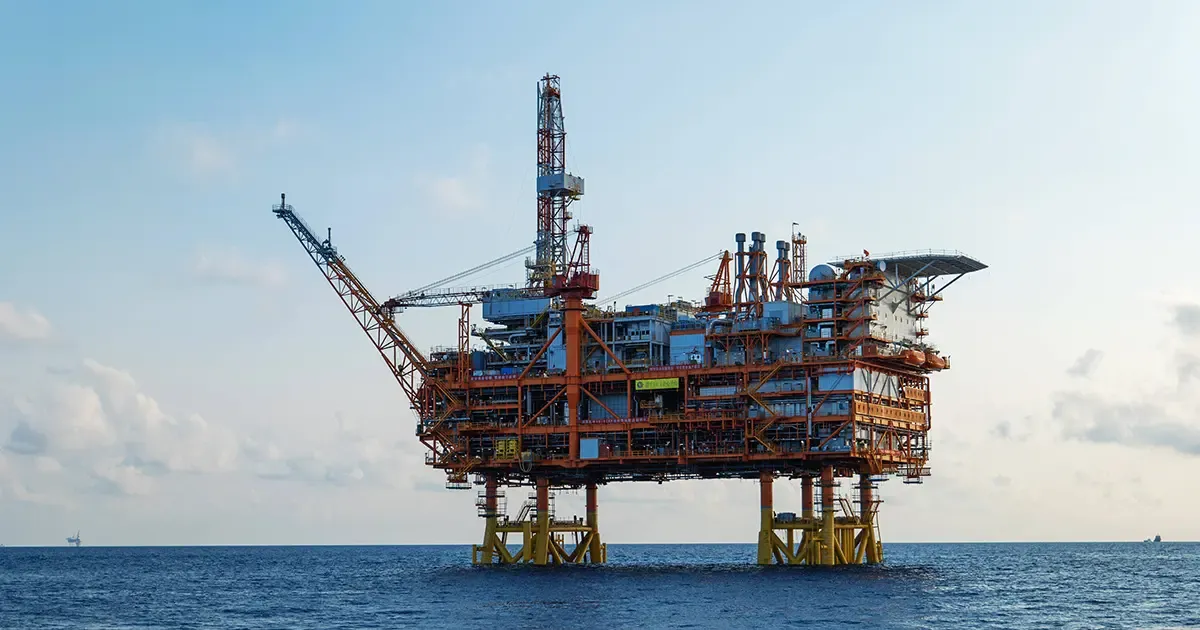
Passive fire protection (PFP) is the part of an offshore platform that does nothing all year, then has to hold the steel together when a hydrocarbon fire breaks out. It is what keeps the escape route cold, the structural steel within its strength window, and the emergency shutdown valves working long enough for the crew to muster and the deluge system to open. Offshore fireproofing is not "fire insulation" in the usual building-services sense — it is engineered blast-, salt-, vibration- and jet-fire-resistant protection sized by rating curve and steel section factor.
On fixed platforms, floaters, or FPSOs, PFP applies to topsides primary structure, pipe racks, drilling-area risers, and any member that can see a high-pressure hydrocarbon leak. For the broader thermal-insulation side of the same offshore asset — process-pipe heat retention, exhaust and turbine casing work — see our marine and offshore thermal insulation reference.
This guide walks through the rating system, the zones that need protection, the materials that actually get specified (intumescent coating vs. fire blanket vs. flexible wrap), and the offshore-specific installation rules that decide whether a PFP system survives a North Sea winter or a warm-water splash zone.
The Rating System: H-60, H-120, J-60, J-120
Offshore PFP is specified against two fire curves and two time tiers, giving four rating combinations that turn up in nearly every project specification:
| Rating | Fire curve | Time | Where it is used |
|---|---|---|---|
| H-60 | Hydrocarbon, ISO 834 | 60 min | Process pipe racks, vessel skirts, secondary structure |
| H-120 | Hydrocarbon, ISO 834 | 120 min | Compressor decks, large hydrocarbon storage, primary escape-route steel |
| J-60 | Jet fire, UL 1709 | 60 min | High-pressure hydrocarbon valves, manifolds, hazardous-area pipework |
| J-120 | Jet fire, UL 1709 | 120 min | Drilling-module risers, wellhead areas, high-consequence jet-fire zones |
The core standard is ISO 13702:2024 (fire and explosion control on offshore production installations), with GB/T 20660-2020 covering the equivalent Chinese offshore requirements and API RP 14G supporting the original risk-based design logic. The rating an engineer picks is driven by the section factor of the steel (Hp/A, the heated perimeter divided by cross-sectional area): thinner steel sections heat faster and therefore need more PFP thickness for the same rating.
Jet fire is the curve that catches projects off guard. A UL 1709 cell-fire reaches about 1093 °C inside five minutes and delivers roughly 204 kW/m² of incident radiant heat — an order of magnitude beyond what a passive building-services fire rating assumes. Anything that can see a high-pressure leak (ESDV manifolds, blowdown valves, riser isolation) needs J-rating, not H-rating.
For the rating-vs-spec layer where PFP meets thermal insulation on risers and process pipework, the A-60 marine insulation guide goes into the bulk heat-balance and casing-temperature side; PFP is the other half of that same wall. For the shipboard side of the same subject — A-class divisions, fire-rated bulkheads and accommodation boundaries — our marine fire insulation guide covers the SOLAS material rules in detail.
Where the PFP Goes: Zone-by-Zone Layout
A typical offshore platform is divided into PFP zones that line up with — but are not identical to — the process modules and the fire zones. The same fire compartment can carry different PFP ratings on different members depending on what that member does during a fire:
- Living-quarter façade facing process — A-rated walls and claddings with PFP on the structural columns and beams of the LQ side. This is also where blast load is layered on top of fire load, so the PFP must be blast-tolerant as well as fire-stable.
- Process module primary structure — H-120 on legs and primary beams, H-60 on secondary beams and grating supports. Compressor and pump skids are usually H-120 around the casing, dropping to H-60 on the supporting steelwork.
- Pipe racks and ESD valve manifolds — J-60 around the valves and the first 450–500 mm of connecting pipe, dropping to H-60 along the rest of the run. This is the typical "shoulder" transition where engineers get caught using one rating across the whole line.
- Drilling and wellhead areas — J-120 on the BOP stack supports, the riser isolation valves, and any structural member within sight of a high-pressure release.
- Escape routes — TEMPSC stations, lifeboat embarkation, refuge areas — H-120 on the supporting steel of the muster deck, the route down to the boat deck, and any walkway that is on the only available evacuation path.
- Helideck supporting structure — H-60 minimum, often H-120 on primary columns, designed to keep the deck load-bearing under crash-fire fuel-pooling scenarios.
Where a process module also carries thermal insulation for heat-rate or anti-condensation reasons — for example the casing of a gas-turbine exhaust or HRSG section piped back to a platform — the combined cycle power plant insulation spec covers the bulk thermal side, and the PFP brings the rating side. The two layers stack on the same steel and must be chemically compatible.
Anti-condensation thickness on those lines is calculated from dew point rather than from a fire curve, and the same applies to accommodation acoustics and LNG cold service — our non-fire marine insulation thickness and acoustic targets guide gives the calculation and the tables.
Materials: What Actually Goes on the Steel
Three PFP families compete for offshore specification. Each has a real niche, none is a universal substitute.
Intumescent epoxy fireproofing
A two- or three-coat epoxy system that swells into a protective char when heated. It is the default for offshore process modules because it:
- Adds the lowest dead-weight per rating point (typically 5–15 mm for H-60, 15–25 mm for H-120 on heavy sections).
- Tolerates salt spray when correctly applied over a compatible primer.
- Holds blast overpressure up to roughly 1.0 bar without spalling, which matters on living-quarter faces and primary process structure.
- Is spray-applied, so it follows complex geometry (valves, brackets, cable-tray penetrations) without joints.
Limitations: solvent-borne systems need controlled application conditions; some epoxy intumescents cannot be immersed and must be top-coated in the splash zone. PFP thickness on intumescent coating is calibrated to the section factor — a heavy column will need substantially less coating than a thin hollow brace for the same rating.
Modular fire blanket / wrap systems
A factory-made blanket of high-temperature fibre (high-alumina or polycrystalline wool, typically 64–128 kg/m³) encapsulated in a foil or glass-cloth facing, supplied as discrete pads, half-shells, or pillow modules that are mechanically banded onto the steel. Used where:
- The geometry is too complex for spray application.
- Rapid installation on a brownfield project matters (modules go on without surface prep beyond cleaning).
- A removable / re-enterable system is needed for inspection of the protected steel.
Thickness is selected to hit the rating curve on the section factor; expect 25–75 mm of total blanket for H-60 to H-120 on heavy structural sections. The facing must be sealed at top and bottom of vertical members — unsealed seams are the most common cause of moisture ingress and corrosion under the blanket.
Rigid fire-board systems
Calcium-silicate board, high-density rock-wool board, or composite boarding used for firewalls, blast walls, escape-route enclosures, and the LQ-facing-process wall. These are mechanically fixed rather than spray-applied. The boards are heavy (calcium silicate at ~200–230 kg/m³), which limits use on elevated decks, but they give a robust, low-water-permeability surface that is easy to inspect and to repair locally.
For most platform PFP projects the specification combines all three: intumescent coating on the structural steel, modular blankets on complex pipework and valve manifolds, calcium-silicate or high-density rock wool blanket board on firewalls and escape-route enclosures.
Radiant Heat and Jet-Fire Shielding
For J-rated zones, the PFP has to defeat a thermal load that does not exist in building-services work. A UL 1709 jet fire reaches 1093 °C in five minutes and 1100+ °C sustained; the incident heat flux on a structure 5–10 m from the leak point is on the order of 100–200 kW/m².
Two design strategies are routine:
- Thickness selection on section factor. For a given rating the relationship between fire-resistance thickness and Hp/A is published by the PFP manufacturer in the form of design tables. Engineers pick the steel section, read off the required thickness for J-60 or J-120, and add a corrosion / wastage allowance. The reason jet-fire PFP looks "thick" is mostly that — J-ratings require substantially more material than H-ratings on the same member.
- Shielding away from the source. Wrapping the first 450–500 mm of pipe leaving a high-pressure valve in a J-rated blanket, while leaving the rest of the line on H-60, produces a workable design without overcoating the whole pipe rack. This is the design philosophy behind ASTM E 1725-tested cable-tray protection, and the same logic applies to instrument tubing and small-bore impulse lines.
CFD fire modelling (FLACS-Fire and equivalent) is now the standard way to confirm that a proposed layout meets ALARP — putting PFP only where the radiant heat map says it is required, instead of coating whole modules out of conservatism. The risk of over-application is real: every extra kilogram of PFP adds to topside weight and to blast design load.
Where the heat load is also a heat-recovery opportunity — for example the casing of a gas turbine or a waste-heat boiler piped back to the platform — the engineering logic overlaps with offshore thermal insulation work in the power module. The same wall often has to perform both duties.
Offshore-Specific Installation Considerations
A PFP system that passes a 60-minute jet-fire test in a lab can still fail on platform if the offshore environment is ignored. Four factors dominate:
- Salt spray and splash-zone exposure. The transition between atmospheric zone and splash zone is where most coating-based PFP systems fail. The fix is a primer-and-topcoat system from the same manufacturer as the intumescent, with documented compatibility. For blanket systems the fix is full banding of seams and a topcoat that resists UV and salt. Periodic visual inspection — typically annual, with closer review after storms — is mandatory under most classification society rules.
- Vibration and mechanical shock. Continuous running of gas turbines, compressors, and drilling equipment vibrates the supporting steel in a 5–50 Hz band. Rigid cementitious PFPs crack; flexible blankets and elastomeric-intumescent coatings survive. Cable penetrations and pipe clamps are the usual failure points.
- Weather windows. Offshore spray-applied PFP needs dry steel, controlled humidity, and a window without rain or sea-spray deposition for the full cure of the primer and the intumescent base coat. Logistics around weather windows are often the real schedule driver on offshore PFP projects — coating chemistry is the easy part.
- Maintenance access. Anything that needs inspection (manifolds, ESD valves, cable joints) must be re-enterable. Bolted-on blanket pillows, removable calcium-silicate panels, and banded modular wraps are designed for this. Sprayed-on intumescent has to be cut and patched.
The installation contractor should hold the manufacturer PFP-application certification, and the field quality plan should record section-factor verification, dry-film thickness on every member, and seam-banding continuity on blanket systems.
Selection Checklist
A short checklist used by most offshore PFP engineers at spec stage:
- Rating for each member: H-60 / H-120 / J-60 / J-120, driven by fire-zone map and ESD valve schedule.
- Section factor Hp/A for each member type — drives thickness on intumescent, blanket, and board.
- Material family for each zone: intumescent coating, modular blanket / wrap, calcium-silicate or rock-wool board.
- Splash-zone treatment at every member crossing the atmospheric / splash boundary.
- Blast tolerance on LQ-facing-process steel and primary process columns (1.0 bar minimum).
- Cable-tray and small-bore-line shielding length: 450–500 mm from the source valve.
- Inspection / re-entry strategy for ESD valves, cable joints, and instrument tubing.
- Compatible primer and topcoat supplied by a single PFP manufacturer, not mixed.
- Field quality plan: DFT logging, seam-banding photos, third-party inspection at handover.
Rosewool supplies modular ceramic fiber blanket and calcium silicate insulation board used in offshore PFP and firewall applications, together with rock-wool and calcium-silicate pipe and board systems for platform process pipework. For offshore fireproofing questions, zone layouts, or thickness calculations tied to your specific fire-zone map, contact our engineering team with your PFP rating schedule and section-factor list.
For a deeper dive into forms, temperature ratings, and application guides, see our ceramic fiber insulation hub.
Frequently asked
What is the difference between H-rating and J-rating offshore? +
H-rating uses the slower ISO 834 hydrocarbon curve and covers general process pipe racks, vessel skirts, secondary steelwork, and escape-route structures. J-rating uses the much faster UL 1709 jet-fire curve and applies to anything that can see a high-pressure hydrocarbon leak — ESD valves, wellhead areas, drilling risers. J-rating typically requires substantially thicker PFP than H-rating on the same member.
How long does offshore PFP need to last in a fire? +
Most offshore PFP is rated for either 60 minutes (H-60, J-60) or 120 minutes (H-120, J-120). The specifier chooses based on fire-zone consequence, evacuation time, and structural redundancy. H-120 and J-120 are used on primary process structure, escape-route steel, and high-consequence jet-fire zones; H-60 and J-60 cover secondary pipe racks and less critical members.
Can normal thermal insulation act as PFP offshore? +
No. PFP has to be rated against a fire curve (ISO 834 or UL 1709) on a defined steel section factor. Standard process insulation such as rock wool or calcium silicate improves the casing temperature but is not tested as a fire rating. Offshore practice is to combine the two: a thermal-insulation layer sized for heat-rate or anti-condensation, with a separate PFP layer sized for the fire rating — sometimes as one composite system, sometimes as two independent systems on the same steel.
What is the most common offshore PFP failure? +
Moisture and salt-spray ingress under the PFP — usually at the unsealed seam of a modular blanket, the cut edge of an applied board, or a damaged intumescent topcoat in the splash zone. The corrosion then proceeds unseen and only surfaces during a scheduled inspection or, worse, during a fire. The second most common is mismatched primer and intumescent from different manufacturers, leading to delamination.
Does intumescent coating or fire blanket work better offshore? +
It depends on the geometry and access. Intumescent epoxy is lighter, follows complex shapes well, and is the default for process-module steel. Modular fire blankets win on complex pipework, valve manifolds, and any member that needs to be re-entered for inspection. Most platforms use both — intumescent on the structural steel, blankets on the valve and pipe-work details.
What standards govern offshore passive fire protection? +
ISO 13702:2024 is the primary international standard for fire and explosion control on offshore production installations, including PFP zoning and rating logic. GB/T 20660-2020 is the equivalent Chinese offshore standard. API RP 14G supports risk-based design language. UL 1709 governs jet-fire testing, ISO 834 governs the hydrocarbon curve, and ASTM E 1725 governs cable-tray fire protection.
Request a quote
Interested in our insulation solutions? Send us your requirements and our team responds within one business day.