
Boiler Insulation: A Zone-by-Zone Guide to Materials, Thickness and Fixing
A zone-by-zone engineering guide to boiler insulation: 14 zones from furnace membrane to flue duct, with material limits, starting thickness and fixing details.
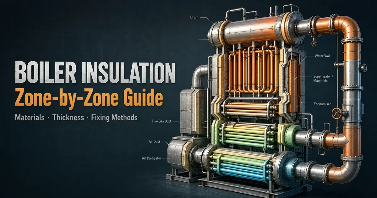
Boiler insulation cannot be selected from a single temperature-and-thickness chart. The same nominal steam temperature can produce completely different insulation demands depending on whether heat flows through a furnace membrane, a horizontal roof penetration, a vertical superheater header, a vibrating economizer casing, a cold-reheat elbow, or a manhole cover. The controlling variables are the local hot-face temperature, the full temperature-dependent conductivity curve, external convection and radiation, cladding emissivity and weather exposure, supports and thermal bridges, access frequency, and the weakest layer - not the material with the highest classification temperature.
Four conclusions govern this guide:
- Classification temperature is not a continuous-service permission. A 1260 °C ceramic fiber grade, a 1100 °C calcium silicate product family and a 650 °C stone wool board each require product-specific continuous-use, shrinkage and ageing data. The calcium silicate product standard covers factory-made material for service up to approximately +1100 °C, but explicitly does not cover the structural performance of the installed system.
- The commonly repeated 80-150 mm main-steam, 40 mm economizer or 100-200 mm drum values are investigation starters - not universal rules. Thickness must satisfy energy, surface-temperature, process-control, space, support and corrosion-under-insulation constraints for the actual pipe or vessel. The standard heat-loss calculation practice is a methodology for well-defined flat, cylindrical and spherical systems, and it warns that accuracy is extremely dependent on the accuracy of the input data.
- Personnel protection is a contact-risk assessment, not an automatic "50 °C rule". The contact-burn assessment standard uses contact material, contact duration, touched area and skin-contact conditions. The often-quoted 43 °C long-contact metal value carries a restricted small-area condition and is not a licence to ignore a 60 °C climbable surface in a congested plant.
- Moisture, voids and bad details usually destroy more performance than a sub-optimal material choice. Water ingress, compressed or fractured board, uninsulated studs, discontinuous vapour control and unsealed cladding joints create thermal bridges and corrosion. For austenitic stainless steel, specify the installed system against the stainless-steel insulation specification and the project coating and corrosion programme; a generic "low-chloride" label is not evidence.
The zone table in Section 4 gives a starting design envelope for each of the 14 zones. Every thickness should be recalculated or at least re-balanced before purchase. The final statement of compliance belongs to the designer, boiler OEM, installer and operator jointly - not to the insulation brand.
1. The Only Valid Selection Sequence: Temperature Driver First, Product Second
A boiler zone should be specified in this order: establish the local thermal driver, determine the acceptable hot-face temperature of each layer, calculate heat flux and external surface temperature, select a build-up whose weakest component clears its certified envelope, and then design the attachment, cladding, drainage and access so the installed system still meets the calculation. Skipping from "main steam is 540 °C" to "use 100 mm calcium silicate" reverses the engineering logic.
The driver is not always the process fluid. In a furnace, the outer membrane temperature is shaped by heat flux, slag and ash resistance, furnace pressure, and whether the wall is water-cooled. In an air heater outlet duct, the gas temperature may be modest but external condensation, acoustic absorption and dust erosion can dominate. On a steam drum, internal saturation temperature is only a starting point; the local shell temperature also depends on pressure, skin effects, orientation, casing air gaps, and solar or wind exposure. On a manhole or relief device, the exposed metal may be far below steam temperature because of conduction through the frame, internal geometry and intermittent flow, but a leaky seat or stagnant steam pocket can invalidate that assumption.
The material-grade number is an upper envelope, never the operating setpoint. Refractory ceramic fiber is marketed in 1100, 1260, 1400 and 1430 °C classification grades. Published product literature consistently distinguishes classification from continuous use and cites shrinkage, thermal cycling, density and atmosphere as reasons to derate; product data commonly describe a 1260 °C blanket as serviceable around 1050-1150 °C depending on purity, and a 1430 °C zirconia grade around 1350 °C. That is product data, not a standard-mandated mapping, and must be checked against the current datasheet and lot certification. Ceramic fiber blanket grades are covered in more depth separately.
Stone wool has an equally rigid but lower boundary: an industrial stone wool board in this class typically declares a maximum use temperature of 650 °C, a nominal density around 128 kg/m³, and temperature-dependent conductivity rising from roughly 0.035 W/m·K at 38 °C mean temperature to about 0.098 W/m·K at 371 °C mean temperature. A different product, density, facing or compressed state will not necessarily reproduce those numbers - check the actual rock wool board datasheet.
Select on the weakest link, then protect it. A 1100 °C hot-face board behind a membrane is pointless if the stud, weld, load-bearing pad or aluminium jacketing fails first. Conversely, a thin aerogel blanket hot-face layer can be justified where space, weight or corrosion resistance matters, provided the underlying asset temperature, jacket and fire performance are validated. Aerogel is not a universal high-temperature material: widely used blanket product families declare a 650 °C maximum use temperature. It is therefore a candidate for hot piping and access-component build-ups, not a substitute for a refractory hot face in a high-radiant furnace zone.
2. What the Standards Actually Prove - and What They Do Not
| Standard / document family | Proper role in a boiler project | Important limitation | Evidence weight |
|---|---|---|---|
| ISO 12241 | Industrial thermal-insulation calculation rules: heat flow, surface temperature, economic thickness. | Does not give a universal zone thickness; results depend on geometry, climate, energy price and conductivity curve. | High for method; no thickness prescription |
| ASTM C680 | Algorithms for heat loss or gain and surface temperature of flat, cylindrical and spherical insulated systems under steady or quasi-steady conditions. | Assumes homogeneous, uniformly dimensioned layers and essentially one-dimensional heat flow; roof penetrations and complex tube shadows need local 2-D checks. | High |
| ISO 13732-1 | Contact-burn-risk assessment: surface material, contact period, touched area. | Not a single global safe-touch temperature; excludes large-area and facial exposure regimes. | High for methodology |
| ISO 8143 | Requirements for factory-made calcium silicate board, pipe sections, segments and prefabricated ware. | "Up to approximately +1100 °C" is a product-family scope, not approval of every board or system. Excludes structural system performance. | High |
| EN 14303 | Product-performance declarations for thermal insulation of building equipment and industrial installations, including reaction to fire. | A declaration is product- and characteristic-specific; it is not a boiler-zone installation manual. | High for product compliance |
| ASTM C533 | Calcium silicate block and pipe insulation; the cited version's scope is 27-927 °C unless otherwise agreed. | Covers particular product forms and tests, not a 1100 °C universal rating for every national grade. | High for scope |
| ASTM C892 | High-temperature fiber blanket insulation: types, grades, conductivity, shrinkage. | Covers blanket forms under its scope; it is not one conformance test for all ceramic fiber modules, boards, paper or castables. | High for blanket forms |
| ASTM C592 | Metal-mesh-covered mineral-fiber blanket and blanket-type pipe insulation; scope includes heated surfaces up to 649 °C for the covered application. | Does not govern every stone or glass wool board, nor fire-resistance systems. | High for scope |
| ASTM C795 + C692 + C871 | Insulation placed in contact with austenitic stainless steel: pre-production stress-corrosion test and chemical quality-control route. | Compliance requires the specified tests and project acceptance; a ppm slogan is not the standard. | High for stainless systems |
| ISO 13787 / EN 13501-1 | Reaction-to-fire testing and classification of products. | "A1 non-combustible" is a classified product claim with a defined test context, not a guarantee that deposited dust cannot burn. | High for fire declaration |
| NACE/AMPP SP0198 | Corrosion-under-insulation control for insulated austenitic stainless steel; system-level coating, material and inspection thinking. | Applicability must be confirmed in the project specification; it does not replace pressure-equipment, local HSE or coating rules. | Moderate-High in scope |
The "no single standard for all ceramic fiber" caveat is precise, not a rejection of standards. A blanket standard exists for high-temperature fiber blanket, and separate standards address particular refractories in certain contexts. But a boiler build-up may combine a ceramic fiber module, a vacuum-formed board, a ceramic paper gasket, a castable and a metal sleeve. Each has its own certified temperature, chemistry, density, shrinkage and compatibility. Procurement should call out the product form and test basis rather than writing "ceramic fiber 1430 °C" as if that were a complete specification.
3. Material Map, Moisture, and the Failure of One-Number Rules
3.1 Material map: grade, driver and derating
| Material class | Practical thermal domain in this guide | Best zone role | Critical selection clause |
|---|---|---|---|
| Ceramic fiber (alumina-silica, high-alumina) | Hot-face furnace, burner nose, refractory backup; grades commonly labelled 1100-1430 °C | Furnace lower wall behind membrane, burner zone, furnace nose, selected roof penetrations | Use continuous-use and shrinkage data for the actual hot-face, not the furnace peak. Cycle life and chemical attack can dominate. |
| Calcium silicate board / segments | Hot structural backup and high-temperature pipework below the product's certified limit | Headers, drum, main and cold-reheat and feedwater pipe sections, casing backup | Product scope is approximately up to 1100 °C; ASTM C533 grades and agreed limits still apply. Confirm strength after heat soak and compatibility with stainless steel. |
| Stone wool board / lamella / blanket | Typically 650 °C or below for the named product class; verify the exact item | Economizer, air preheater outlet duct, flue duct, ESP casing, moderate-temperature casing | A 650 °C limit is a product boundary, not a suggestion to run at 650 °C. Conductivity rises with mean temperature. |
| Glass wool / glass-fiber blanket | Low-to-moderate temperature service; product-dependent upper bound near 400 °C is a common commercial limit | Ambient-side backup, conditioned-space ducts, some indoor cold-service or low-temperature return runs | Do not place in a hot-face role merely because it is glass fiber. Check binder, facing, fire and compression resistance. |
| Aerogel blanket | Space, weight or corrosion-critical hot service; product families commonly capped at 650 °C | Pipe elbows, congested main-steam and hot-reheat runs, access devices, maintenance-sensitive routes | Hydrophobic behaviour helps moisture management but does not replace jacketing, drainage or stainless-steel chemical compliance. |
Glass wool's -120 to +400 °C range appears in manufacturer literature and is useful as a screening clue, not as a code boundary. Below ambient, the design switches from heat loss to dew-point control, vapour diffusion and sometimes freeze protection. Above ambient, binders, facings and compression settle the limit. The same caution applies to "650 °C aerogel": a named product family's declaration cannot be transferred to an unverified aerogel felt or panel.
3.2 Moisture turns a thermal problem into a structural and corrosion problem
Wet insulation is not simply "a bit less insulating". Water raises the solid-matrix heat transfer, can fill pores, create wicking paths, wash soluble species, and keep the outer surface apparently cool while the metal underneath stays wet and warm. In cold-reheat and feedwater zones, a failed vapour retarder can move the dew point into the insulation. In furnace and hot-gas zones, ingress is often intermittent - wash-down, rain through a torn lap, leaking sootblower packing, or condensed flue gas - but the thermal cycling then bakes and cracks the layer.
Moisture claims should therefore be bounded carefully:
- A blanket statement that "wet insulation conductivity rises 5-10 times" should not be used as a design value. The change depends on saturation, temperature, pore structure, freeze state and measurement method.
- Design inputs should include dry and damaged-state thermal conductivity, not only the brochure number.
- Specify jacket lap direction, sealants compatible with service temperature, stainless screw and rivet details, drain-out paths that do not short-circuit the insulation, and a repair protocol.
- For stainless steel, corrosion risk is managed by a system: surface preparation and coating where required, a certified low-leachable material route, dryable construction, inspection and prompt breach repair. The stainless-steel insulation specification requires covered non-metallic insulation to pass pre-production stress-corrosion testing and chemical quality-control requirements when specified for austenitic stainless steel.
3.3 Touch protection: the contact standard defeats the "50 °C rule"
The correct question is not "is the jacket below 50 °C?" but "who touches what, for how long, where, and under which environmental and clothing conditions?" ISO 13732-1 addresses skin contact of 0.5 s and longer, assumes the surface temperature is essentially maintained during contact, and excludes large-body or facial-vital-area exposures. Its procedure is: identify accessible hot surfaces, run a task analysis, measure surface temperature, select the contact-duration threshold, compare, and determine risk.
For uncoated metal, a commonly reproduced part of the standard gives approximately 51 °C at 1 minute, 48 °C at 10 minutes and 43 °C at 8 hours. The 43 °C figure carries a small-area restriction of less than about 10 percent of body or head skin in the cited scope, and is not a plant-wide jacketing target. A climbable platform handrail, a frequently handled valve jacket and a remote roof panel each deserve different task-based criteria. Project HSE rules, local machinery regulations and clothing conditions may impose a stricter numeric target such as 50 °C at 25 °C ambient or ambient plus 30 °C; treat those as client or statutory requirements, not physics constants.
The design consequence is useful: a small high-temperature access cover can be legally and technically acceptable at a higher surface temperature if contact is fleeting, guarded and labelled, whereas a walkable drum lagging run must be designed for prolonged contact and convective warming of the work space. The reverse error - calling a 70 °C guarded remote surface unsafe based on a blanket number - is as bad as ignoring a 55 °C handrail.
4. Zone-by-Zone Engineering Matrix
How to read the table. The temperature driver is the local condition that sets the hot-face material choice, and it is not always the steam or flame temperature. The starting build-up is a procurement and engineering hypothesis for a typical utility or industrial boiler, not a guaranteed-compliance thickness. Fixing and cladding is generic good practice; welding, loading and seismic requirements are project-specific. Where a range is given, the low end is appropriate only when calculation, low external heat flux, benign climate, adequate support and easy rework allow it.
| # / Zone | Temperature driver (local, not necessarily fluid temperature) | Preferred / alternative build-up | Starting thickness / design rule | Fixing and outer protection | Dominant risk and inspection detail |
|---|---|---|---|---|---|
| 1 | Furnace lower waterwall / membrane | Hot-face ceramic fiber module or board, or compatible castable refractory backup, then high-temperature board. Alternative: dense refractory hot face in slag-impingement zones. | Do not use a fixed millimetre rule. Start with a furnace heat-flux model and the membrane exterior and refractory cold-face temperatures; the hot face must stay below the product continuous limit with margin. | Modules on alloy anchors sized for thermal expansion; staggered board joints; load-bearing pads independent of pressure-part welds where practicable; inner casing or refractory air seal. | Slag erosion, flame impingement, anchor oxidation, membrane shadowing. Lower walls can see severe cycling; a claim that the membrane runs above 800 °C must be measured or derived, not assumed. |
| 2 | Burner zone / furnace nose | Ceramic fiber or high-alumina module, or shaped refractory hot face plus backup. Avoid stone wool at the hot face. | Hot-face grade and build-up are set by peak local refractory and cold-face temperature, burner oscillation, start-stop cycles and fuel ash chemistry. | Anchors in a pattern that accommodates differential movement; compression joints at corners; access doors with retained hot-face shape. | Highest thermal shock and flame or ash attack. Nose geometry creates two- and three-dimensional heat flow and deposit accumulation; calculate, then verify with startup infrared imaging. |
| 3 | Furnace roof / penthouse and roof-tube penetrations | Hot-face refractory or ceramic fiber module where radiant; high-temperature calcium silicate or verified board backup in cooler pockets. | The penetration is the controlling detail: establish tube-skin, refractory and casing temperatures separately; a uniform roof blanket thickness is usually wrong. | Tube-penetration collar, slip or radial expansion gap, non-crushing sleeve, separate roof deck and penetration builds; stainless mesh or cement only where the system is validated. | Dust and delamination on hot ledges can smoulder even if the insulation is non-combustible. A1 classification is a product declaration, not a cleaning waiver. Check for steam and water leaks at tube welds. |
| 4 | Steam drum | High-temperature calcium silicate board or segments on the shell; aerogel or stone wool backup only if interfaces stay in the certified range. | Published 80-120 mm and 100-200 mm figures arise from different pressures, saturations, diameters, casing and loss targets. Start from the conductivity curve, shell diameter, ambient and support loads; a large high-pressure drum commonly needs more than a small low-pressure drum, but diameter alone is not the rule. | Load-bearing high-density blocks or cradles at supports; independent support rings where needed; banding or permanent casing with removable manhole and handhole frames. No stud loads that compromise shell integrity. | Cyclic wet and dry, manhole thermal bridge, heavy casing sag and corrosion at support shoes. Remove selected covers during outage to check the shell and block crush. |
| 5 | Headers (superheater, reheater, water, steam) | Calcium silicate pipe segments for cylindrical runs; shaped high-temperature board at discontinuities. Aerogel may reduce envelope at elbows. | Start from header outside diameter, saturation or steam temperature, bend density and access. A thin single layer everywhere fails at tappings, welds and support brackets. | Segmented bands, circumferential stagger, stainless banding or lock rings; hinged or bolted removable covers at inspection ends; anti-vibration supports. | Hundreds of penetrations and thermal expansion make headers corrosion- and leakage-sensitive. Design for repeated removal without crushing the hot layer. |
| 6 | Superheater and reheater zones (casing compartments, tube banks) | Hot-face ceramic fiber or refractory where radiant and exposed; calcium silicate backup on casing walls; stone wool only where the cold face is proven below the product limit. | Begin from local gas and skin temperature, not the steam nameplate. Pendants and horizontal runs have different convection and deposit conditions. | Anchored modules or boards with expansion gaps at casing stiffeners; removable access panels; mesh only as the system calls for. | Tube-to-header shadowing and casing hot spots. Image the casing at steady load; a hot rectangle often means a compressed corner or missing backup, not necessarily a tube problem. |
| 7 | Economizer | Stone wool board or lamella, or calcium silicate where temperatures justify it; aerogel only if the cost and space case holds. | A figure of 40 mm is a familiar estimator for moderate gas and metal conditions, but not a code thickness. Recompute for gas inlet and outlet, finned tubes, casing orientation and wind. | Board or mesh system suited to casing vibration; separate access panels over tube rows; cladding laps that shed water. | Fin and tube vibration, ash abrasion, condensate at low load, and hidden voids behind the casing. Tie thickness to dew point and economizer bypass risk, not just fuel saving. |
| 8 | Air preheater and outlet duct | Stone wool or glass wool product validated for the actual gas and external conditions; avoid hot-face ceramic fiber unless a high-temperature pocket exists. | The air preheater outlet can be cool enough that economic thickness is thin, yet external condensation may govern. Design for the coldest credible ambient and part-load gas temperature, not only the rated outlet. | Pinned board system or internal and externally accessible lining; sealed jacket, drain points, expansion joints at duct breaks. | Cold-end corrosion and acid dew point plus moisture ingress dominate. Aerogel's hydrophobic character helps only as part of a drained, jacketed system. |
| 9 | Main steam and hot-reheat piping | Calcium silicate pipe sections as the workhorse; aerogel or composite for congested and high-value routes; stone wool only where the full hot-face profile is certified. | Typical published ranges of 80-150 mm span many pipe sizes, pressures, steam temperatures and jacket conditions. Iterate heat flux and surface temperature for each nominal bore and bend; elbows, valves and supports are separate calculations. | Split semicircular segments, circumferential stagger, stainless banding, clevis and strut supports that do not crush insulation; 0.5-0.8 mm aluminium jacketing is a common indoor starting point, stainless where weathering or corrosion demands it. | Expansion loops, valve remakes, stainless chemistry and support spacing. Pre-insulated pipe shoes and pads must be part of the thermal and structural model. |
| 10 | Cold-reheat steam piping | Calcium silicate or a qualified stone wool or aerogel build-up; often thinner than main steam at similar size because of lower temperature, but not automatically. | Start from actual cold-reheat temperature and ambient, then check warm-up, trip and solar or wind cases. A 50-80 mm figure is an experience-based starting range only. | Same pipe-section discipline, with removable valve and actuator jackets and insulation breaks at expansion devices. | Low-temperature excursions and condensation during start and stop make corrosion and vapour control more important than the steady heat loss alone suggests. |
| 11 | High-pressure feedwater piping | Calcium silicate or a qualified stone wool or aerogel build-up; glass fiber backup only on the cold side of a composite if certified. | Typical published 40-60 mm ranges are a budgeting aid. At 200-280 °C class fluid temperatures, small-bore lines can have high surface-area-to-volume ratios, so economic thickness may be thin; outdoor cold start and dew point may reverse that. | Banding, insulation shoes, vapour-retarder continuity where required, aluminium or stainless jacket per exposure. | High-pressure small-bore failures are often corrosion or erosion at supports. Do not let a low-temperature label justify skipped stainless controls or crushed heel pads. |
| 12 | Boiler casing (wall, roof and floor enclosure) | Hot zones: ceramic fiber or refractory hot face plus calcium silicate backup. Cooler zones: stone wool board; glass wool only in validated low-temperature cold-face service. | Thickness follows furnace pressure, gas-to-casing heat transfer, external orientation and allowable heat flux or surface temperature. Double-layer boards are common; the oft-cited 50-75 mm is not a global casing minimum. | Welded studs or nails with tested base-metal compatibility, self-locking washers or impedance-welded clips, stainless mesh where needed, two layers with staggered joints, then casing or jacket. | Air leakage, casing flex, stud thermal bridges and water trapping. A continuous inner air or membrane seal can matter more than adding another 25 mm. |
| 13 | Flue duct and electrostatic precipitator | Stone wool or glass wool per actual gas and external climate; do not import furnace hot-face materials by habit. | Calculate separately for inlet (hot, possibly acidic) and outlet cold-end conditions. The controlling case may be acid dew point, rain, dust abrasion or acoustic treatment, not fuel savings. | Internal lining where designed, or external board, pin and mesh with weather jacket; allow duct shell inspection and dust clean-out. | Acid condensation, dust hold-up, corrosion and vibration. An A1 product does not stop acid attack of the duct; specify materials and drainage for the flue-gas chemistry. |
| 14 | Access and relief devices: manhole, handhole, sight port, furnace door, explosion door | Composite local build-up: hot-face refractory or ceramic fiber at the furnace door; calcium silicate, stone wool or aerogel in a removable jacket for drum and header covers; gasketing matched to temperature and emission path. | Never assume an uninsulated cover equals steam temperature. Measure the outer plate or calculate from frame conductivity, internal convection and contact resistance. Removable cover thickness is a custom detail, often limited by frame, seal and handling. | Bolted or hinged removable covers, captured insulation cassette, anti-crush frame, high-temperature gasket and compression stop, lanyard or lift point. Explosion doors must move; do not bond them shut with cement or over-tight cladding. | Repeated removal destroys continuity. Design for a five-minute correct rebuild, not a pretty one-off. Relief and furnace doors need clear mechanical operation and a thermal path that does not warp the seat. |
The most important comparison in the table is zone 4 versus zone 9. A drum and a main-steam pipe can both see roughly 540-565 °C fluid, yet the drum has a large radius, a horizontal climbable surface, supports, manholes and long hold times, while the pipe has elbows, shoes and a different surface-area-to-heat-capacity ratio. That is why 100-200 mm drum mineral wool and 80-150 mm main-steam pipe ranges can both appear in vendor guidance without being interchangeable.
5. Build Quality: Joints, Anchors, Loads and Cladding Decide the Real Conductivity
5.1 Two layers are a default, but the joint rule is a workmanship control
For flat or gently curved high-temperature casings, a two-layer system lets the outer layer bridge studs and breaks the continuous path created by a single layer's saw cut. The widely used practice of staggering adjacent-layer joints by at least 100 mm is a sound workmanship objective where geometry permits, but it is not a universal code-prescribed dimension for every boiler, curvature or product. Specify it in the inspection and test plan, then adapt to nozzles, tube spacing and panel size. On small-radius pipe elbows, a 100 mm stagger may be geometrically meaningless; there, joint location, segment overlap and band placement matter more.
The layer order must follow temperature gradient and mechanical role:
- Hot face: rated for the local continuous temperature, peak holds and chemical environment; capable of accepting the anchor system.
- Backup: compatible conductivity curve, compression set and joint geometry; not assumed to be just filler.
- Separation or mesh: used where the system needs handling strength or to control delamination, not as a thermal cure-all.
- Cladding or jacket: weather, impact, appearance and emissivity control. It must not crush the insulation or bridge expansion.
5.2 Anchors and studs are thermal bridges that must be designed, not hidden
A welded stud, a stainless mesh, a band and a cladding screw each short-circuit part of the insulating layer. The correct response is not to eliminate all attachment - that creates a greater loss and a safety hazard - but to:
- use the minimum number and smallest practical cross-section consistent with load, seismic and wind cases;
- select stud alloy and weld procedure for the local temperature and base metal; do not weld arbitrary alloy pins to pressure parts without OEM and integrity review;
- keep stud layout compatible with board and module dimensions so joints do not coincide with a line of concentrated load;
- specify self-locking washers, impingement or spot-welded clips, or captive retainers per the product system;
- isolate load-bearing cradles and supports from the insulation where a shoe carries pipe weight; the insulation may be a thermal filler around the shoe, not the structural hanger.
For drums and headers, a high-density block, purpose-made cradle or metallic support insert is normally required at the true load path. Compressing a standard 128 kg/m³ stone wool board to carry a drum saddle is not an acceptable shortcut. The same logic applies to heavy access doors: hinge loads belong to the frame, while the insulation cassette floats or is positively retained without relying on friable board edges.
5.3 Expansion, vibration and penetrations are where one-dimensional calculations fail
A one-dimensional calculation model is excellent for a uniform cylindrical pipe or flat casing bay, but it cannot by itself resolve a roof-tube collar, a header branch cluster, a refractory corner or a casing stiffener. These locations need one of three responses: a local two- or three-dimensional thermal model, a conservative derate with a higher-temperature inner system, or an explicit prototype and start-up measurement programme.
At every penetration:
- maintain a controlled annular expansion gap sized for differential growth, not a wad of loose fiber;
- use a high-temperature sleeve or seal system compatible with both the tube and the casing;
- prevent the outer jacket from constraining the inner refractory;
- detail weep and drain paths so that any ingress does not sit against the tube;
- verify that the roof detail is not a horizontal dust shelf. A non-combustible calcium silicate board or an A1-classified product removes one fuel source, but deposited combustible dust, oil mist or char can still create a fire concern. Cleaning access and a no-trap geometry are therefore fire measures too.
5.4 Jacketing: aluminium is common, but the exposure case chooses the metal
Aluminium sheet in the 0.5-0.8 mm range is a frequent indoor boiler and pipe jacket starting point because it is light, formable and quick to install. It is not a universal choice. Use stainless where chloride, coastal or chemical environment, high jacket temperature, frequent wash-down or mechanical durability demands it; use galvanized steel only where the service temperature, cut-edge protection and compatibility with the insulation and substrate are explicitly acceptable. Bare aluminium and galvanized steel are not interchangeable, and stainless mesh does not make a carbon-steel jacket suitable for a chloride environment.
Generic good detailing:
- longitudinal seams oriented and shielded to shed water; on outdoor horizontal runs, avoid an upward-facing open lap;
- overlaps of at least 50 mm are a common minimum detailing practice, not a guarantee of watertightness;
- circumferential bands or ties approximately every 300 mm are a useful starting spacing for many jacket runs, but wind, panel size and vibration can require closer spacing or intermediate supports;
- seal only with compatible high-temperature tapes and sealants; a generic silicone may be fine indoors at low temperature and catastrophic at a furnace-roof penetration;
- terminate jacket edges so water cannot wick behind the insulation; provide drain relief rather than sealing all sides.
More detail on cladding and jacketing is covered separately.
6. Calculating Thickness, Surface Temperature and Savings Without Lying
6.1 The calculation inputs that actually change the answer
For each zone, collect:
| Input | Why it matters | Typical mistake |
|---|---|---|
| Fluid temperature and local metal or gas temperature | Fluid can be cooled by heat transfer or insulated by deposits | Using steam temperature for a furnace wall or a remote duct |
| Inner and outer diameters, flat-panel thickness, curvature | Cylinder maths changes with radius | Using flat-sheet conductivity directly on a small pipe |
| Conductivity curve for every layer, including aged state | Curves diverge at high mean temperature | Using one 25 °C value |
| Jacket emissivity and colour | Radiation can dominate the outer balance | Treating all aluminium jackets as equal |
| Indoor or outdoor ambient, wind, sun, rain | External convection governs surface temperature and condensation | Designing for still air in a coastal boiler house |
| Orientation and posture | Heat rises; roofs and undersides differ | Using the same thickness for top, side and soffit |
| Duty cycle, start-up and trip | Thermal shock, dew point and corrosion occur off-design | Optimizing only at full load |
| Supports, studs, seams, penetrations | They add heat leak and create hot spots | Calling the model installed performance after a perfect drawing |
| Energy price, run hours, discount rate, replacement cost | Economic thickness is a cost optimum, not a thermal maximum | Claiming a fixed payback for all plants |
The standard calculation practice explicitly notes that wind velocity, jacket emittance, ambient conditions and other parameters must be accounted for, and that results are only as good as the inputs. Economic-thickness work minimizes total annual cost: installed capital, maintenance and replacement, and energy loss over the selected study period and operating profile. The curve can shift dramatically if the boiler runs seasonally, if aluminium prices rise, or if access is difficult. The general method is set out in the insulation thickness calculation guide and in the economic thickness selection guide.
6.2 "Every 1 percent less heat loss equals 1 percent less fuel" is wrong
Let L0 be the pre-retrofit insulation heat loss as a fraction of fuel heat input, f the fraction of that loss eliminated by the retrofit, and eta the overall boiler thermal efficiency on the same fuel basis.
The incremental fuel saving is then:
fuel saving (percent) = f x L0 x (100 / eta)
So if insulation loss is 2 percent of fuel input and the retrofit halves it (f = 0.5), the fuel saving at an efficiency of 88 percent is 0.5 x 2 / 0.88 = 1.14 percent of fuel input. If insulation loss is only 1 percent of input, halving it saves about 0.57 percentage points of fuel. This is why a credible proposal must state the baseline insulation-loss share, not merely the expected heat flux in W/m².
The oft-quoted "boiler heat loss is 1-3 percent of input" can be a useful screening range for a reasonably insulated shell and piping envelope, but it is not a law and certainly not a warranty. It depends on load, size, surface area, fluid temperatures, casing leaks, and what is counted - shell only, or also valves, flanges, ducts and uninsulated auxiliaries. A small high-temperature process boiler with missing valve covers can lose far more through fittings than a well-lagged utility drum. Never convert a 1-3 percent number into a project payback without a measured or calculated baseline.
Likewise, W/m² is geometry-dependent. A 250 W/m² shell criterion may be appropriate to a client's heat-loss specification, while a 300 W/m² limit may be acceptable elsewhere; neither is inherently universal. For piping, compare heat loss per unit length in W/m as well as W/m² and external surface temperature. A thin small-bore line can pass a W/m² target while still wasting more energy per metre than a thick large line, and vice versa.
6.3 Which target comes first?
Run the calculation against all applicable constraints and pick the thickest compliant build-up, not the cheapest one that satisfies only energy:
- Process and equipment limit: every layer's hot-face and cold-face temperatures stay within certified continuous service.
- Structural limit: compression, support, vibration and anchor load path remain acceptable.
- Personnel limit: project touch criterion based on task analysis.
- Moisture limit: external surface and internal dew-point cases avoided where required; corrosion strategy applied.
- Energy and economic limit: heat flux or heat loss target and life-cycle optimum.
- Fire, emission and regulatory limit: classified products and local fire and plant rules.
- Constructability: available module width, bend geometry, stud weldability, access and repair time.
7. Installation, Verification and the Lagging Vocabulary
7.1 Field controls that should appear in the inspection and test plan
| Stage | Minimum check | Failure consequence |
|---|---|---|
| Material receipt | Grade, lot, certified maximum service temperature, conductivity curve, density, fire and stainless test status, dimensions | Substitution of a 650 °C board into a hot-face role; incompatible filler |
| Surface preparation | Clean, dry substrate; correct coating and cure state; no loose scale at stud welds | Coating failure, stud pull-out, hidden corrosion |
| Hot-face layer | No crushing, correct anchor embedment, expansion gaps, compatible sleeves | Shrinkage gaps, spalling, hot spots |
| Backup and stagger | Joints offset; no continuous through-crack; density-uniform cut pieces | Linear thermal bridge and premature jacket heating |
| Load path | Shoes, cradles and pads independent of insulation where specified | Permanent set, bare-metal contact, casing deflection |
| Mesh and jacket | Correct fastener alloy and edge distance; lap direction; sealed ends | Mesh sag, water ingress, cladding flutter |
| Accessories | Manhole, handhole, sight glass, valve, actuator and relief-device covers rebuildable | Covers left off after the first outage |
| Completion | Infrared baseline at stable load, plus visual walk-down and lift-check of panels | Hidden void passed as insulated |
A double layer with joints staggered at least 100 mm, mesh and bands at 300 mm should be read as a quality starting pattern, not a substitute for an attachment design. Stud spacing, weld size, clip type and band load must come from the insulation system supplier's tested detail and the boiler OEM's restrictions. Where the pressure part is involved, welding permits and inspection are non-negotiable.
7.2 Infrared thermography finds symptoms, not root causes
Use infrared as a comparative tool at steady load, with a calibrated camera, known emissivity, and records of load, wind, sun and surface condition. A hot spot can mean:
- compacted or missing insulation;
- an uninsulated stud, band or bracket;
- an internal refractory void or slag bridge;
- water in the layer;
- a leaking flange or valve stem;
- local flame impingement or tube fouling;
- external solar heating on a dark panel.
Do not issue a replace-all-insulation work order from one thermal image. Trend the same point over load and time, compare symmetrical zones, then open a small investigation window. The standard calculation practice specifically anticipates using infrared inspection, in-situ heat flux measurements or both to evaluate operating systems. Heat flux is particularly valuable when surface temperature is ambiguous because of wind or high emissivity variation.
7.3 "Boiler lagging" is a term, not a material class
In UK and Indian plant parlance, boiler lagging commonly means the complete external insulation and protective covering system: the insulating mass plus cement, wire mesh, studs and the outer metal casing or lagging sheets. It is not a distinct physical product category alongside calcium silicate, stone wool and ceramic fiber. An old British specification might call for a particular thickness of block lagging finished with cement and steel casing; an Indian site might refer to drum lagging, pipe lagging or L-section pipe covering. Modern procurement should translate that language into material form, performance curve, fixing system and cladding requirements. Otherwise a contractor can supply a technically different product that still satisfies the word lagging.
8. Retrofit and Outage Strategy: Add a Layer Only When the Diagnosis Supports It
8.1 Add, re-skin, or strip and rebuild?
| Observation | Usually correct action | Do not |
|---|---|---|
| Intact boards, dry, no crush; heat flux or surface temperature slightly high | Add a compatible outer layer only after checking jacket and anchor capacity and joint stagger | Pile new blanket over oil-soaked old material |
| Cracked boards, powdering, shrinkage gaps, wet base layer | Remove to sound substrate, rebuild the hot-face system, then recalculate the total build-up | Hide a failed hot face behind a cosmetic jacket |
| Localized stud or bracket hot spot | Redetail the thermal bridge and repair the substrate; add local insulation only if the anchor stays in specification | Double the whole zone because one bracket glows |
| Recurring corrosion on stainless or carbon steel | Open inspection, test and prove coating and insulation chemistry, improve drainage and seal plan | Specify low chloride by brand name alone |
| Repeated cover removal at valves and manholes | Convert to a properly engineered removable cassette | Cement the access shut for a neater finish |
| High surface temperature after a process change | Re-run the calculation for new maximum load, trip and ambient cases | Assume the old 25 mm increment still works |
8.2 Replacement triggers should be condition-based and tied to failure modes
A useful outage decision matrix is:
- Replace if there is sustained hot-face temperature excursion beyond the certified continuous limit, significant linear shrinkage or delamination, chemical attack, compression set that leaves a metal-to-metal path, wet rot, biological or oil contamination, or loss of fire declaration integrity.
- Repair locally only if the substrate and adjacent layers are sound, the patch uses compatible chemistry and conductivity, joints are staggered, and the repaired zone passes infrared and heat-flux trending.
- Recalculate and often rebuild after a fuel switch, major load-profile change, pressure-part modification, casing pressure change, or a new ambient or wind exposure condition.
- Keep the old cover if it is a genuine reusable, labelled, undamaged cassette system - but verify dimensions and fasteners. A cover that has been cut, crushed or soaked is no longer a reusable asset.
The outage window should be long enough for cool-down, safe entry, substrate inspection and coating work, a trial rebuild of the worst penetration, and a hot restart infrared baseline. Rushing the curing, heat-up or anchor-weld inspection trades a short outage for a roof penetration failure at half load. Follow the refractory and insulation manufacturer's heat-up schedule and the boiler OEM's thermal ramp limits.
9. A Procurement Specification That Prevents Catalogue Engineering
A robust purchase line item should contain the following minimum information, even where the boiler OEM already supplies a general arrangement:
- Zone and geometry: for example "furnace lower wall, bay 3, outside of membrane, flat or radius, dimensions, orientation, casing pressure".
- Thermal driver: design, maximum load, start-up and trip temperatures at the hot face; gas or fluid temperature alone is inadequate.
- Product identity and form: product code, board, blanket, module or segment, density, and lot-traceable certificates. "Ceramic fiber 1430" is not enough. Reference the actual ceramic fiber module or blanket form.
- Temperature evidence: certified classification temperature and continuous-service recommendation, shrinkage test conditions, and the conductivity curve including aged data.
- Chemical and corrosion evidence: the stainless-steel test route for austenitic stainless where applicable; soluble chloride, fluoride and sodium declarations; coating compatibility.
- Fire and emissions: the project-required reaction-to-fire declaration, with the exact product and facing or jacket combination.
- Mechanical system: anchor type, alloy, weld procedure, spacing, mesh, washers, cradles, allowable loads and expansion gap.
- Cladding system: metal type and thickness, finish, lap, sealant, fasteners, band spacing, drainage and wash-down compatibility.
- Performance deliverables: calculated heat flux, external surface temperature, interface temperatures and economic-thickness basis; as-built infrared baseline; test and inspection records.
- Removability: marked removable panels and covers at every manhole, handhole, sight port, sampling point, drain, valve, actuator and relief device.
If a supplier objects to providing the conductivity curve, the continuous-use recommendation or chemistry documentation, the product is not ready for a high-consequence boiler zone. If a contractor proposes a single thickness for all 650 °C zones, the proposal is not yet an engineering design. For budget screening across material families before this level of detail is fixed, the industrial insulation cost comparison gives indicative ranges.
10. Final Engineering Disclaimer
Final insulation thickness and build-up must be determined from the specific design case: actual local hot-face and cold-face temperatures, certified conductivity and continuous-service limits, density and compressibility, cladding emissivity and weather exposure, climate, support and seismic loads, available space, access frequency, corrosion and dew-point regime, fire classification, and an energy-economic calculation. Construction must comply with the boiler OEM, applicable pressure-equipment and welding rules, local building, fire and HSE regulations, and the project specification. Where two- or three-dimensional effects, roof penetrations, refractory interfaces or thermal bridges dominate, use a validated thermal model or measured hot-face and cold-face commissioning data rather than extrapolating the zone table. The values in this guide are deliberately conditional engineering starting points, not a permit-to-work or a replacement for site-specific design.
Related reading: calcium silicate pipe insulation, oven and kiln door insulation, and the combined cycle and gas turbine plant guide. Power generation applications are collected under power generation insulation.
Frequently asked
Can I use a 1260 °C ceramic fiber grade wherever the furnace temperature is below 1260 °C? +
No. The classification temperature is not a continuous-running permit. Check the actual local hot-face temperature, hold time, thermal cycles, shrinkage, atmosphere and anchor system. A 1260 °C label can conceal a product whose continuous use is materially lower, and a hot membrane can be much cooler than the flame while still needing a robust backup system.
Is a 50 °C outer surface always safe? +
No. ISO 13732-1 makes contact risk depend on material, contact duration, touched area and exposure conditions. A 50 °C aluminium panel can burn a hand that grips it for long enough, while a brief brush against a guarded 60 °C surface is a different task. Apply the project personnel-protection criterion rather than treating 50 °C as a physical law.
Why do steam drum insulation recommendations range from 80-120 mm to 100-200 mm? +
Those ranges encode different drum diameters, pressures and saturation temperatures, casing geometry, ambient conditions, allowable heat flux, walkway and touch requirements, and structural build-up. A high-pressure large drum with a climbable top and heavy casing may need more insulation and load-bearing blocks; a small low-pressure drum in a warm indoor space may need less. Neither range is universal.
Is 40 mm correct for every economizer? +
No. Forty millimetres is a familiar budgeting start for moderate-temperature, moderate-climate conditions, but the inlet can be much hotter than the outlet, finned tubes change external heat transfer, and cold-end dew point may control the design. Model the zone in at least two operating cases and inspect after the first low-load period.
Does an uninsulated manhole or safety relief cover sit at steam temperature? +
Not as a general rule. The outer cover temperature depends on internal convection, seat and stem conduction, gas versus steam exposure, contact resistance, orientation, and whether the device is passing flow or stagnant. Measure it, model the frame, and provide a removable insulated cassette sized for touch protection and unobstructed mechanical operation.
Will aerogel automatically cut boiler insulation thickness by half? +
Sometimes, in space-constrained high-value piping. Aerogel's thinner profile is valuable only if its certified temperature limit, compressive behaviour, jointing, jacket, fire performance and cost fit. A named product family still has a 650 °C maximum-use boundary, so it is not a furnace hot-face substitute.
What does A1 non-combustible actually protect against? +
It is a classified reaction-to-fire and product-performance claim under a defined test and declaration system. It does not mean deposited coal dust, oil mist or other combustibles cannot burn on the surface, and it does not remove the need for roof-penetration sealing and housekeeping.
How do I convert a measured 280 W/m² hot spot into a fuel saving? +
First confirm the area, load, duration, and whether the 280 W/m² is steady. Then calculate the pre- and post-retrofit loss in kW, multiply by operating hours and fuel heat value, and apply boiler efficiency as in section 6.2. Never multiply 280 W/m² by a guessed surface area and call it one percent of fuel saved.
What is the right stud, mesh and band spacing for boiler insulation? +
There is no global answer. Spacing is set by panel size, density, orientation, vibration, wind, jacket gauge, anchor weld capacity and the supplier's validated system. Use 100 mm joint stagger, 50 mm laps and about 300 mm band spacing only as stated starting practices, then adjust to the calculation and the approved fixing schedule.
Which standard should I cite to approve a boiler insulation material? +
Cite the standard that matches the product form and the claim: ISO 8143 or ASTM C533 for calcium silicate, ASTM C892 for high-temperature fiber blanket, ASTM C592 for covered mineral-fiber blanket, EN 14303 for declared industrial product performance, and ASTM C795, C692 and C871 for austenitic stainless contact risk. Then attach the actual manufacturer certificate. A standard's existence does not approve an unverified product.
Request a quote
Interested in our insulation solutions? Send us your requirements and our team responds within one business day.