
Combined Cycle & Gas Turbine Power Plant Insulation: Materials & Spec
Spec guide for combined cycle power plant insulation — gas turbine exhaust, HRSG zone-by-zone materials, pipework thickness calculation, CUI protection, and vibration-zone installation.
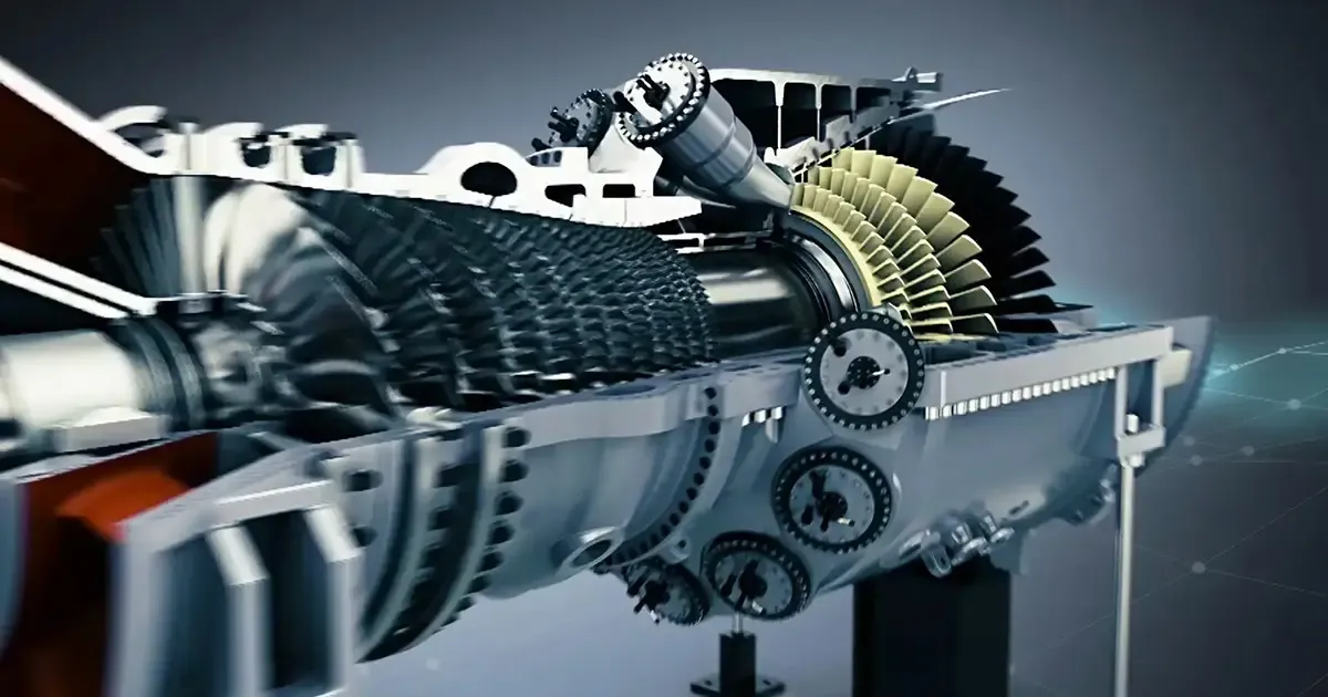
A combined cycle power plant (also called a CCGT plant or natural gas combined cycle plant) pairs a gas turbine with a heat recovery steam generator (HRSG) and a steam turbine. The gas turbine burns natural gas, the hot exhaust passes through the HRSG to make steam, and the steam turbine produces additional electricity. Insulation is not a finishing touch here — power plant thermal insulation is what decides the heat rate, the casing temperature the operator can touch, and whether the HRSG tubes fail early from corrosion.
This guide to combined cycle power plant insulation walks through the specification for a modern combined cycle plant: which material belongs in each temperature zone, how to size pipework insulation for power plants, why corrosion under insulation (CUI) is the dominant reliability risk, and how to install insulation where vibration and thermal cycling are routine.
Plant Layout and Temperature Zones
A typical 400–800 MW combined cycle plant contains four distinct thermal zones, each with its own insulation requirement.
| Zone | Component | Operating temperature | Dominant constraint |
|---|---|---|---|
| 1 | Gas turbine combustor | 1600–1800 °C | Not user-insulated; ceramic thermal-barrier coating only |
| 2 | Gas turbine exhaust / diffuser | 600–700 °C | Lightweight, vibration-resistant lining |
| 3 | HRSG hot pass / superheater | 500–650 °C | Thermal-shock resistance, hot-face durability |
| 4 | HRSG economiser, ductwork, stack | 150–500 °C | CUI prevention, operator-touch safety |
Insulation choice in zones 2–4 is what determines performance, fuel cost, and unplanned outage frequency. If you are sizing a new build or auditing an existing plant, work zone by zone. A single specification across the whole plant leads to over-specification in cool areas and under-specification at the hot face.
For a broader view of insulation across the wider plant — boilers, substations, nuclear auxiliaries, offshore wind — see our guide to rock wool in the power industry and the application hub for power generation insulation.
Gas Turbine Exhaust and Diffuser (600–700 °C)
The gas turbine exhaust is the most demanding zone that the user actually insulates. Exhaust gas temperature (EGT) is normally 580–620 °C for modern F-class machines, rising to 650–700 °C on hot days or at full load. The exhaust flows through a diffuser and duct into the HRSG inlet, where every degree of heat loss is energy that never reaches the steam cycle.
The exhaust diffuser is typically lined with light-weight refractory material — usually a ceramic fiber blanket or module behind a metallic casing. The fibre is chosen for three reasons:
- Light weight — adds minimal load to the turbine skid and foundation.
- Low thermal mass — survives frequent start-up and shutdown cycles without cracking.
- Low thermal conductivity — even a thin layer captures most of the radiant heat in the diffuser.
Material specification for this zone usually calls for alkaline-earth silicate fibre (AES) or standard aluminosilicate fibre blanket with a classification temperature of 1260 °C, density 96–128 kg/m³, and shot content below 15 %. The blanket is supported on stainless steel pins welded to the casing, with the cold face protected by a galvanised or aluminium jacket. For very high EGT or cyclic operation, specify higher alumina content fibre (60 % Al₂O₃) or a polycrystalline wool module for additional stability.
Behind the diffuser, transition ductwork drops in temperature from ~600 °C at the HRSG inlet toward ~500 °C where the superheater tubes begin. This region is commonly insulated with rock wool blanket (operating cost is lower than ceramic fibre here) faced on the cold side with aluminium to prevent air infiltration. Where the duct passes through personnel-access areas, surface temperature must stay below 60 °C — calculate the required thickness from the duct surface temperature, not from a nominal hot-side number.
HRSG High-Temperature Section (500–650 °C)
The HRSG high-temperature section is the most material-intensive part of the plant. Hot flue gas leaves the gas turbine at 580–650 °C, passes over the superheater (typically 10–12 m of finned tubing) and reheater, then drops to 350–450 °C before entering the evaporator bank.
At this temperature range, the dominant insulation choices are:
- Ceramic fibre blanket or board (classification temperature 1260 °C, density 128–160 kg/m³)
- High-purity ceramic fibre with 1260–1430 °C grade for cyclic service
- Calcium silicate board as a structural backup layer where the casing needs to carry load
The hot pass — the section directly above the superheater tubes — is the hardest region. Flue gas temperature here can swing by ±55 °C during load changes, and thermal cycling at every start-up and shutdown drives fatigue. Vacuum-formed ceramic fibre shapes or pre-fabricated modules are preferred because they keep joints closed even after thousands of cycles. For very tight geometries around tube bends, pre-formed ceramic fibre pipe sections reduce installation time and eliminate the gaps that lead to hot spots.
Where the casing includes personnel access or walkways, multilayer construction is standard: 50 mm of ceramic fibre on the hot face for thermal resistance, backed with 50–80 mm of rock wool blanket or calcium silicate board for compressive strength and personnel protection. The cold-face layer is the one operators ever touch, so it must be sized for surface temperature, not for thermal loss.
For the matching pipework, our calcium silicate pipe section is rated to 1000–1050 °C and gives a rigid, A1 non-combustible outer layer for the superheated-steam lines leaving this zone.
HRSG Mid and Low-Temperature Sections (200–500 °C)
Below the superheater, temperatures drop into the range where the insulation for power plants spec becomes more about corrosion prevention than thermal performance. The evaporator bank runs at 350–450 °C, the economiser at 200–300 °C, and the air-preheater / stack section at 150–200 °C.
In this range, rock wool is the standard choice. Standard density 80–120 kg/m³ rock wool blanket, faced with aluminium or stainless steel cladding, gives a robust, repairable lining that meets personnel-protection surface-temperature limits at typical thicknesses of 80–120 mm. Calcium silicate board can be used where rigidity helps — for example on duct corners, equipment pads, or anywhere the lining needs to support cladding weight without sagging.
CUI is the dominant failure mode in this zone. Flue gas carries water vapour, and the casing surface temperature often passes through the dew point during shutdown. Wet insulation in contact with carbon steel casing accelerates external corrosion. Mitigation is built into the specification: hydrophobic rock wool, sealed joints, drained cladding, and an air gap between insulation and casing where geometry allows. More on this in the CUI section below.
Hot Pass and Ductwork (500–610 °C)
The hot pass region of the HRSG — between the gas turbine outlet and the superheater — deserves special mention because the geometry is unforgiving. Tube bundles, support brackets, headers, and inspection ports create a complex three-dimensional shape. Insulation here must:
- Wrap tightly around thousands of finned tubes without leaving exposed hot spots.
- Tolerate thermal expansion of the tubes (several millimetres per cycle).
- Resist vibration from flue gas pulsation.
- Be removable for periodic tube inspection.
Vacuum-formed ceramic fibre shapes, pre-fabricated modules, and ceramic fibre blanket with stainless steel wire mesh are the typical solutions. The specification usually calls for stitching the modules to stainless steel anchors welded to the casing, with ceramic fibre paper gaskets at every joint to absorb expansion. Density 160–192 kg/m³, classification 1260 °C, shot content under 12 %.
Typical thickness in this zone is 100–150 mm. At those thicknesses, ceramic fibre modules become the most efficient install — they are made to drawing, dropped into position, and compressed 10–15 % against the casing to lock in place. Field cutting is minimised, joint quality is consistent, and the casing can be reassembled in the same configuration at every outage.
Pipework Insulation Thickness Calculation
Pipework thickness in a combined cycle plant is sized by one of three methods.
Economic thickness method balances the capital cost of insulation against the present value of heat loss over the asset life. It applies to all heat-traced and untraced lines carrying hot fluids or steam.
δ = √[(h₁ · ΔT) / ((k · ρ · c · ΔT) / (C · P · E · L))]
where δ is economic insulation thickness, h₁ is the surface-to-air heat-transfer coefficient, ΔT is the temperature difference, k is thermal conductivity, ρ is density, c is specific heat, C is material cost per kilogramme, P is energy price, E is plant efficiency, and L is asset life.
Surface-temperature method limits the outer cladding temperature to 60 °C in operator-access areas or to the dew point in unheated outdoor locations to prevent moisture condensation.
Condensation-control method (also called the balance method) prevents condensation on chilled-water and cryogenic lines. It is less relevant for combined cycle steam lines but applies to air-preheater piping and condensate returns.
For routine plant work the practical rules are:
| Service | Pipe size | Recommended insulation thickness |
|---|---|---|
| High-pressure steam (450 °C, 100 bar) | DN 100–300 | 80–120 mm ceramic fibre or rock wool |
| Medium-pressure steam (250–350 °C) | DN 80–200 | 60–80 mm rock wool |
| Hot water (150 °C) | DN 50–150 | 60–80 mm multilayer |
| Boiler feedwater (95–105 °C) | DN 50–200 | 40–60 mm rock wool or glass wool |
| Condensate (60–80 °C) | DN 50–150 | 40–50 mm glass wool |
In coastal or high-humidity sites, increase these thicknesses by 10–15 % to keep the cold-face temperature above the dew point and reduce CUI risk. The extra cost is repaid many times over in avoided casing corrosion.
A worked example for a typical HRSG high-pressure steam line (DN 150, 450 °C, ambient 25 °C, ceramic fibre with k = 0.04 W/m·K, density 180 kg/m³) gives δ ≈ 70 mm by the economic thickness method. In practice, the installed thickness is 80–100 mm because line geometry, supports, and valve bonnets require local increases to 120–150 mm.
For pre-formed pipe sections, our rock wool pipe and calcium silicate pipe products cover the full DN 15 to DN 500 range with single-layer and multi-layer construction.
Corrosion Under Insulation (CUI)
CUI is the single largest cause of unplanned outages on insulated carbon-steel equipment in power plants. The mechanism is straightforward: water penetrates the insulation, reaches the casing surface, and stays there at 60–150 °C — the ideal temperature range for aqueous corrosion.
The risk is highest on equipment that cycles through the dew point: economisers, feedwater heaters, air-preheater casings, and outdoor piping in seasonal climates. Failure modes include pitting, stress-corrosion cracking on austenitic stainless components, and through-wall perforation of carbon-steel casings. The economic cost is severe: a single casing replacement during an unplanned outage can exceed the entire lifetime savings from the insulation.
CUI prevention is built into the specification in three places.
Material selection. Use closed-cell or hydrophobic insulation where wetness is expected. Hydrophobic rock wool repels water but breathes; calcium silicate is dimensionally stable even when damp. For critical services — offshore platforms, coastal plants, equipment subject to wash-down — specify closed-cell products such as aerogel blanket or foam glass, both with hydrophobicity ≥ 98 %.
Structural design. Maintain a 25–50 mm air gap between the casing and the insulation where geometry allows. Drain any condensation to the outside of the cladding. Use sealed lap joints on the cladding, not exposed butt joints. At flanges and valves, use removable insulation boxes that can be lifted for inspection without destroying the permanent lining.
Inspection regime. CUI is invisible until it is too late. Specify removable insulation at flanges and inspection points, install tell-tale coupons on critical casings, and add visual inspection points every 5–10 m on long pipe runs. A 30-minute walk-down during a planned outage is far cheaper than a casing replacement.
| Insulation type | Hydrophobicity | Thermal conductivity @ 25 °C | Service life | Use case |
|---|---|---|---|---|
| Aerogel blanket | ≥ 98 % | ≤ 0.021 W/m·K | ≥ 10 years | Critical CUI zones, thin-layer retrofits |
| Foam glass | ≥ 98 % | 0.03–0.04 W/m·K | 15–20 years | Underground piping, cryogenic |
| Calcium silicate (dry service) | Moderate | 0.055–0.060 W/m·K | 20+ years | Steam piping, dry-service equipment |
| Rock wool (hydrophobic grade) | ≥ 98 % | 0.034–0.040 W/m·K | 15+ years | Boiler casings, general industrial |
Vibration Zones
Three regions in a combined cycle plant experience continuous or intermittent vibration that destroys ordinary insulation.
Gas turbine exhaust diffuser. Combustion pulsation and thermal expansion drive structural vibration at low frequency but high amplitude. Aerogel blanket or compressed ceramic fibre board, mechanically fixed with stainless mesh and banded in place, is the typical specification. Adhesive-only fixing fails within months; mechanical fixing is mandatory.
Steam pipe flanges and valve bonnets. Differential expansion between the pipe and its supports creates cyclic movement at every load change. Removable insulation boxes with inner metallic frames are the only durable solution. The box is held by quick-release straps so it can be lifted in minutes for inspection.
Steam turbine inlet piping. High-velocity steam flow induces vibration in the insulation mass itself, leading to settlement, gaps, and hot spots above the pipe. Dense ceramic fibre board (≥ 192 kg/m³) anchored with welded pins is preferred; flexible blankets are unsuitable.
At each of these zones the specification adds 10–15 % to the calculated insulation thickness to compensate for loss of effective coverage over time. Where this is done poorly — using the same nominal thickness as static zones — premature failure is the rule, not the exception.
Case Studies from Operating Plants
Delayed-coker retrofit at a major Chinese refinery. A steam line operating at 480 °C was insulated with 130 mm of alkaline-earth silicate fibre. Surface temperature was 16 °C above ambient and inspection revealed heavy external corrosion on the casing. The line was re-insulated with 70 mm of nanoporous aerogel blanket. Surface temperature dropped to 5 °C above ambient, heat loss fell by about 65 %, and the casing corrosion risk was eliminated by the closed-cell structure.
Drying kiln in a chemical plant, northern China. A 30 m rotary kiln shell was running at 190 °C with a traditional mineral wool lining, losing more than 1 M RMB of gas per year per kiln. A 2–3 mm nanoporous aerogel coating replaced the original lining. Shell temperature dropped to 75 °C within hours of application, heat loss fell by 32 %, and the annual gas saving exceeded 0.9 M RMB per kiln. Payback time was less than 12 months.
HRSG superheater header, 600 MW combined cycle plant. Field conditions: header at 540 °C, original insulation 130 mm of AES fibre, frequent cracking at inspection-port joints. The header was re-insulated with pre-formed ceramic fibre modules to drawing, density 192 kg/m³, classification 1260 °C. After two years of cyclic operation the modules showed no measurable settlement, hot spots at inspection ports were eliminated, and outage time for boiler inspection fell by 40 %.
These are retrofit numbers from real plants. New builds should design for these gains from day one rather than capturing them later.
Selection Checklist
For an insulation specification on a new combined cycle plant, the following items belong on the datasheet:
- Zone-by-zone temperature range (exhaust, hot pass, evaporator, economiser, stack).
- Maximum continuous service temperature for each zone, including cyclic peaks.
- Insulation type and form for each zone (blanket, board, module, pipe section).
- Density, classification temperature, and shot content for ceramic fibre.
- Hydrophobicity for any insulation exposed to outdoor or condensing service.
- Outer cladding material and joint detail — aluminium, galvanised steel, or stainless steel.
- Removable insulation at flanges, valves, and inspection points.
- CUI mitigation — air gaps, drainage, sealed joints, inspection access.
- Acoustic target for the diffuser and intake (typically 85 dBA at 1 m).
- Surface temperature limit in operator-access zones (60 °C in most jurisdictions).
The datasheet must be specific to the plant. A spec copied from another project — or from a generic supplier brochure — will fail in the field.
Bottom Line
Combined cycle and gas turbine power plant insulation is one of the highest-leverage decisions in plant design. Get it right and you keep the heat rate stable, avoid CUI-driven outages, and protect operators from hot surfaces. Get it wrong and you pay for it in fuel cost, maintenance, and unplanned shutdowns for the next 25 years.
The specification follows a clear logic: material follows temperature, form follows geometry, density follows mechanical load, and cladding follows environment. Apply that logic in every zone, pay particular attention to CUI prevention and vibration-zone fixing, and the lining will outlast the plant.
Rosewool has supplied rock wool pipe, calcium silicate pipe, ceramic fiber blanket and module products for combined cycle plants since 1982, with full ISO 9001, CE, and SGS certification. Contact our engineering team for zone-by-zone datasheets, pipe-thickness calculations, and CUI risk reviews for your specific plant.
For detailed pipe-thickness tables on the boiler and steam side of a power plant, see our power plant insulation materials and thickness guide.
Explore flexible aerogel and microporous insulation options in our aerogel insulation guide.
Frequently asked
What is combined cycle power plant insulation? +
Combined cycle power plant insulation is the thermal insulation applied to the gas turbine exhaust, the HRSG (heat recovery steam generator), steam piping, and ancillary equipment. Its role is to reduce heat loss, keep surface temperatures safe to touch, and prevent corrosion under insulation (CUI).
Which insulation material is used in the HRSG high-temperature section? +
The HRSG high-temperature section (500–650 °C) is insulated with ceramic fibre blanket, board, or pre-formed modules. Classification temperature is typically 1260 °C, with higher-purity grades (1430 °C or polycrystalline wool) used in cyclic or high-EGT service.
How thick should pipe insulation be in a combined cycle plant? +
As a working rule, high-pressure steam lines (450 °C, DN 100–300) need 80–120 mm of insulation, medium-pressure steam (250–350 °C) needs 60–80 mm, and hot water (150 °C) needs 60–80 mm. Economic thickness calculation is preferred for final sizing; the values above are field-typical starting points.
What is CUI and how is it prevented? +
Corrosion under insulation (CUI) is external corrosion of carbon-steel equipment caused by water trapped against the casing at 60–150 °C. It is prevented by using hydrophobic or closed-cell insulation, an air gap between casing and insulation, sealed cladding joints, drainage paths, and removable insulation at inspection points.
Why is aerogel blanket used in some combined cycle retrofits? +
Aerogel blanket has very low thermal conductivity (≤ 0.021 W/m·K at 25 °C) and closed-cell hydrophobic structure. In retrofits it lets designers cut insulation thickness by half while lowering surface temperature, and the closed-cell structure eliminates CUI risk on critical casings.
Which insulation material is used in vibration zones? +
Vibration zones — gas turbine exhaust diffuser, pipe flanges, steam turbine inlet piping — require dense ceramic fibre board (≥ 192 kg/m³) anchored with welded pins, or aerogel blanket banded in place with stainless mesh. Adhesive-only fixing is not durable in these regions.
Request a quote
Interested in our insulation solutions? Send us your requirements and our team responds within one business day.