
Ceramic Fiber Module Installation & Anchoring Guide
How to install and anchor ceramic fiber modules: folded vs stacked construction, centerline anchoring, alloy limits by tip temperature, spacing, QC checkpoints and lining failure fixes.
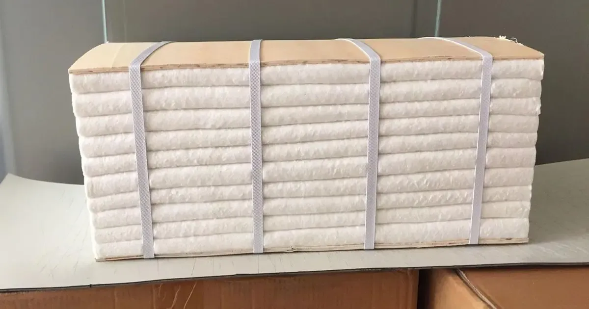
A ceramic fiber module is a pre-compressed, self-locking insulation unit, and that is exactly why installation quality decides everything. The module system carries its spring-back inside the block: remove the restraining bands at the wrong moment, orient the compression axis the wrong way, or let an anchor stud run hot, and a lining that looked flawless on handover will open gaps within the first heat cycles. This guide organizes module installation and anchoring the way refractory engineers actually make the decisions: module construction first, then anchoring system and alloy, then layout, sequence, quality control and failure diagnosis. (For polycrystalline-fibre modules — a different, higher-temperature product class with different handling rules — see our dedicated PCW module specification and installation article.)
Why Installation Decides Lining Performance
A module lining is not "blankets nailed to the shell". It is a designed system in which fibre orientation, pre-compression, controlled rebound, shrinkage compensation and the local temperature of metal anchor components interact. The module stores elastic strain in the factory; the installation either preserves that strain in a useful, engineered state or destroys it.
Three consequences follow, and every section of this guide is built on them:
- The rebound only works in the fold direction. A folded module is a continuous needle-punched blanket serpentine-folded and compressed into a block. The elastic reserve lives in the fold plane; the lateral faces of the block hold no comparable reserve. Rotate a module within a row, or present a cut face as a hot face, and you have silently deleted the sealing function.
- The metal must stay cold. Anchors are the skeleton of the lining — and the only metallic parts exposed to heat. Every anchor decision is a heat-transfer decision: keep the metal tip below the alloy limit, or accept the failure chain that follows.
- Shrinkage must be compensated, not wished away. All alumino-silicate fibres shrink irreversibly over time at temperature. The system design answers this with compression reserves and compensation strips — not with "tight-looking" joints at handover.
Folded Modules vs Stacked Blanket Modules
The two dominant module constructions share one logic — folded or layered blanket, pre-compressed, held by internal anchors near the cold face — but differ in how they manage the hot face.
Folded (serpentine) modules. A continuous strip of needle-punched blanket is folded back and forth into a waffle-like block, compressed to a specified density, and banded. Stainless base hardware and a central anchor channel sit on the cold side. After positioning, the bands are cut and the folds expand against neighbouring blocks, closing joints under contact pressure. The hot face is a series of continuous folded layers with the fold orientation running through the thickness — favourable for roofs and vibrating environments because the continuous fibre network holds the face together. Key handling rules: install every module with the compression axis aligned per the approved drawing, keep the folded face as the hot face, and never treat the central anchor hole or any cut edge as a working surface.
Stacked (layered) modules. Layers of needle-punched blanket are stacked to thickness and anchored — either with short hardware that grips only the cold layers, or with through-thickness hardware carrying washer plates at the hot face. Through-anchoring shortens the metal path to the hot side: installation is faster and module replacement is easier, but the washers, pin heads and punched holes sit closer to the heat. Cold-face-only anchoring keeps the heat bridge short but concentrates load in fewer points.
Density and erosion. Module densities around 128, 160 and 192 kg/m³ are all common international options — there is no single "correct" module density. Higher density improves surface durability and resistance to gas wash-out; it also raises conductance slightly and adds load on roof anchors. Low-density modules rebound beautifully but erode faster under high-velocity, dust-laden gas. Match density to gas velocity, dust load and position in the furnace, not to a catalogue default. Where velocity or splash exceeds what any fibrous hot face tolerates, the answer is structural — a denser hot-face layer, rigid fibre board, or a composite lining — not more coating. (Material-level trade-offs against other furnace insulators are covered in ceramic fiber vs rock wool for furnaces.)
Classification Temperature Is Not Service Temperature
Module datasheets lead with classification temperature — commonly 1260 °C, 1400 °C or 1430 °C for alumino-silicate grades. Classification is a laboratory grading based on permanent linear change at test temperature, not a continuous-use rating. Well-established engineering practice treats actual continuous service in oxidizing or neutral atmospheres as roughly 100–250 °C below the classification temperature, and in reducing atmospheres roughly 200–350 °C below it, with exact margins depending on chemistry, purity, thickness, atmosphere and cycling.
Site temperature guidance for ceramic fibre therefore lands around 1100–1350 °C continuous for standard and high-purity grades, with zirconia-enhanced grades extending toward the top of the family range. Beyond pure temperature, the dominant ageing mechanism is crystallization: amorphous alumino-silicate fibre progressively devitrifies to mullite and cristobalite above roughly 1000 °C, which drives the irreversible shrinkage that opens module joints. This is why compensation design (below) matters more than datasheet temperature.
| Decision variable | What raising it buys you | The cost or boundary | Engineering conclusion |
|---|---|---|---|
| Fibre grade / purity | Higher long-term stability, lower shrinkage | Cost, wider supply variance | Select on actual hot-face peak, dwell time and atmosphere first |
| Module density | Erosion resistance, surface durability | Higher conductance, more roof load | Denser at the hot face; optimize the cold end; never uniform by rule |
| Pre-compression | Joint sealing pressure, shrinkage reserve | Over-compression kills rebound; under-compression opens joints | Follow the module's specified compression state — "tighter is safer" is false |
| Thickness | Lower cold-face and anchor-tip temperature | Weight, anchor bending moment, shell deflection | Compute jointly with anchor spacing and alloy |
| Coatings / hardeners | Wash-out and spark resistance | Can crack, spall, add weight; not fibre-compatible universally | Approved systems only, trial panels first |
Anchor Systems: Centerline, Washer Plates and Hot-Face Exposure
Centerline anchoring pulls each module to the shell through hardware embedded inside the block, close to the cold face. The metal sits deep in the insulation gradient, so anchor-tip temperatures stay low, the hot face shows no metal, and shell heat losses drop. The costs: pre-compression and locking must be executed precisely, and a single mis-positioned stud or unseated nut compromises the whole module. Most high-temperature, continuously operated furnaces — and all heavily loaded roofs — justify the precision.
Washer-plate (butterfly) anchoring uses flat plates fixed through or over the fibre layers, fastened to the shell. Installation is fast, holding area is large, and individual module replacement is straightforward. The metal, however, sits nearer the hot face: plates heat up, holes in the fibre around them create local density discontinuities, and if the hot face wears back, exposed plates become point heat bridges and erosion initiators. Best suited to mid-temperature zones, frequently maintained areas and positions where the tip temperature can be verified acceptable.
Hot-face anchor exposure is a failure mode, not a design feature — unless the system was explicitly designed and qualified for it. The classic degradation chain runs: exposed tip oxidizes and thins → heat bridge grows → local shell hot spot → adjacent fibre shrinks faster → gas wash attacks the metal → anchor breaks → module drops. When you find burned anchors, do not just weld new studs into the old holes beside powdered fibre. Diagnose local temperature, atmosphere and gas velocity first, then choose: a higher alloy, deeper embedment, ceramic insulating caps, or a conversion to cold-face anchoring. Simply "using a fatter stud of the same alloy" usually fails, because the larger cross-section conducts more heat.
Anchor Alloys: Select by Tip Temperature, Not Furnace Temperature
The most common anchor mistake is selecting the alloy from the furnace operating temperature instead of from the actual temperature at the hottest point of the metal — the exposed or near-exposed tip. Industry quality-control guidance for refractory fibre linings (notably API Std 976 practice) makes this explicit: anchor material shall be selected for the maximum service temperature at the exposed component tip, every anchor shall receive 100 percent visual inspection with physical testing, and welds shall be made on clean surfaces by qualified welders with traceable consumables.
Widely published tip-temperature ceilings for common anchor materials:
| Anchor material | Approximate tip-temperature ceiling | Practical note |
|---|---|---|
| 304 / 316 stainless | ≈ 760 °C | Do not let "stainless steel" into a hot-anchor list by name alone |
| 310 stainless | ≈ 927 °C | Common high-temperature choice; verify atmosphere — sulphur and carburizing service erode the margin |
| 330 alloy | ≈ 1038 °C | For high-stress roofs and higher tip temperatures |
| Alloy 601 (Ni-Cr-Fe) | ≈ 1093 °C | Near the practical ceiling for metallic anchors in fibre linings |
Two atmosphere warnings override the table. High-nickel alloys lose strength in sulphur-bearing atmospheres; high-chromium grades can be the better answer there, subject to welding and embrittlement review. And in carburizing service, standard high-temperature alloys carburize and embrittle well below their ceiling — the design data must come from the alloy producer for the actual atmosphere, stress and required life. Weld consumables must match the anchor and the shell; joining high-alloy studs with carbon-steel wire without procedure qualification is a prohibited shortcut.
Welding quality control is part of anchor selection. For a furnace with thousands of studs, "it looked welded" is not a check. Enforce: cleaned and ground shell surface at every weld location; positioning templates; test welds at shift and welder changes; 100 percent visual inspection of every stud; physical checks (bend or torque) on a documented sampling plan per an approved inspection and test plan; re-verification of projection length and squareness before module closure.
Layout: Spacing, Roofs, Corners and Penetrations
Published practice for blanket linings gives wall spacing around 254 mm across the blanket width and 254–305 mm along its length, tightening toward 254 mm for severe vibration. Treat those numbers as a screening reference only — they are not automatic module-anchor spacing. Module width, thickness, pre-compression, fibre orientation, embedment depth, roof load and shell stiffness all differ; anchor spacing for a module lining comes from the module supplier's approved drawings and load calculations, not from a generic table.
Rules that hold across systems:
- Roofs carry self-weight plus thermal cycling plus creep. Anchor pull and fibre sag are worst here; expect closer spacing, higher alloys and explicit creep checks on stud extension.
- Corners, doors, burner blocks, peep doors and penetrations create double-sided shrinkage and cut edges. Reinforce with factory-formed corner modules, additional anchor points or approved cutting plans — not by cramming several studs into one fibre zone.
- Never create a continuous straight joint of two cut faces. Two facing cut surfaces have no rebound between them; stagger or compensate them like any other shrinkage path.
- Edge distance matters. A module trimmed back until its anchor sits close to the hot face has lost both embedment and insulation of the metal.
Installation Sequence and Quality Control
A disciplined sequence — layout, shell preparation, stud welding with inspection, backup layers, module positioning, locking, compensation, band removal, trimming, dry-out — turns a fragile fibre system into a twenty-year lining. The table below is a contracting-grade checklist; adapt tolerances to the project specification.
| Stage | Must-verify items | Acceptance state / record |
|---|---|---|
| Material receipt | Grade, density, dimensions, batch, banding integrity, moisture, certificates | Matches purchase spec; wet or damaged modules quarantined for supplier assessment |
| Shell preparation | Rust, oil, weld spatter, hole positions, flatness, anti-corrosion | Clean and weldable; repairs closed out before lining |
| Layout | Module boundaries, openings, corners, anchor coordinates | Checked against approved drawings; key dimensions re-measured |
| Stud welding | Welder qualification, procedure, cleanliness, squareness, projection, weld size | 100% visual; physical test per ITP; first-batch test welds passed |
| Backup layers | Layer count, orientation, staggered joints, compression | No through-joints; specified thickness reproduced |
| Module setting | Compression direction, anchor engagement, pre-load/locking, sequence | No forced cutting, no fibre damage by hardware, both signatures |
| Compensation & band removal | Strip grade/thickness, compression, fixing, removal timing per procedure | Joints hold reserve; no single module expanded freely |
| Hot-face trim | Holes, joints, bulges, spall risk | Surface flush; hot-face fibre continuous |
| Dry-out & first heat | Heating curve per supplier, shell temperatures, joint widths, anchor condition | Approved curve followed; anomalies assessed before service |
Details that decide outcomes: modules slide onto studs with alignment guides, never forced sideways across fibres; walls build from the bottom up, roofs in approved zones with completed modules stabilized before neighbours are unbanded; locking hardware tightened to the specified pre-load or travel — never to an improvised universal torque; and the shell is prepared to a recorded cleanliness grade, because anchor welds inherit every oxide layer you leave behind.
Compensation, Band Removal and First Heat-Up
Compensation strips manage lateral shrinkage. Where the fold rebound cannot close a joint direction — between rows, against burner blocks, at roof-to-wall junctions — install compressed counter-strips of the same fibre grade or an approved compatible one, sized for the designed lateral shrinkage over the service interval plus relaxation and installation tolerance. Strips must be mechanically held (stapled, pinned or retained per the approved system); loose fibre stuffed into a joint is temporary maintenance, not compensation.
Band removal timing follows the supplier's written procedure — there is no universal order. Remove bands too early and unanchored modules expand freely into incomplete neighbours, producing bulges; too late and modules bind against structure or hardware, never reaching their designed compression state. The general logic — position, lock, compensate, then release — holds; the exact step order belongs to the module system.
Dry-out is the first thermal acceptance test. Water, binder residues and coating solvents must leave the lining on a controlled curve; runaway heat-up builds steam pressure that blisters and spalls fibre. Record shell temperatures, soak plateaus, steaming locations and crack development. Handover geometry only proves the cold state — rebound, compensation, anchors and shell behaviour are proven by the dry-out and the first heat cycles. Establish an infrared baseline of the shell at representative hot spots now, because every later inspection will be compared against it.
Common Failure Modes: Fix the Cause, Not the Symptom
| Failure mode | Visible symptom | Root cause chain | Corrective priority and action |
|---|---|---|---|
| Anchor overheating | Shell hot spots, discoloured or thinning tips | Tip temperature above alloy limit; hot-face exposure | P1 if hot face exposed or shell hot: change system (deeper embed, higher alloy, ceramic caps), not just the stud |
| Roof creep / sag | Modules dipping, anchor displacement | High-temperature stress on undersized anchors | P1: unload, support, replace, re-verify spacing and alloy |
| Weld failure | Single module loosening, cracked welds | Dirty surface, poor procedure, shell movement | P1: cut out, re-weld to procedure; surface build-up welding is prohibited |
| Shrinkage gaps | Through-joints leaking flame or gas | Devitrification shrinkage, missing compensation | P2: pack same-grade compressed strips; re-check grade and anchor temperatures |
| Thermal bridging | Local high shell temperature | Exposed hardware, oversized or too-shallow anchors | P2: measure tip temperature, then insulate, deepen or convert anchoring |
| Fibre crystallization / powdering | Brittle face, dust, strength loss | Continuous temperature beyond grade, long dwell | P2: regrade the zone and trace true peak temperature — surface repair alone repeats the failure |
| Erosion / wash-out | Pitting, thinning, exposed anchors | Gas velocity and dust beyond density class | P2: structural fix — denser hot face, rigid board or composite layer; low spots are temporary fills |
| Vibration fatigue | Loose hardware, joints reopening | Sparse anchoring under equipment vibration | P1/P2: tighten the layout and treat the vibration source; adhesive is not a fix |
| Chemical attack | Vitrified or blackened face, holes | Alkali, sulphur, halide or salt deposits | P1/P2: sample and analyze, then regrade; coatings cannot reverse matrix damage |
| Compression errors | Slack joints or bulged modules | Wrong pre-load, wrong band-removal timing | P2: re-set before dry-out; assess thermally after |
When modules drop, the root-cause ranking is almost always: anchor temperature or creep, weld quality or surface cleanliness, insufficient pre-compression or anchor count, shell vibration, then hot-face puncture exposing metal to flame. Replacing the fallen block without checking neighbouring anchors, shell condition and heat-up history usually schedules the next failure.
Specifying Modules: What to Demand from Suppliers
Procurement should bind four tables into the contract. Material: fibre chemistry class, classification temperature and test basis, density, thickness and dimensions, permanent linear shrinkage, thermal conductivity curve, batch certificates. Anchoring: alloy grade, dimensions, embedment depth, projection, welding method and consumables, inspection frequency, traceability. Installation: cleanliness grade, layout, welding sequence, backup construction, compression and locking, compensation, band-removal procedure, trimming, coating program. Acceptance: material traceability, weld records, process photographs, final dimensions, shell infrared baseline, dry-out curve and post-dry-out defect list.
For grade-level selection across the whole furnace insulation family — including where ceramic fibre modules stop being the answer — start with the best heat-resistant materials for furnaces overview and the refractory insulation board selection guide; for a heavy industrial application walk-through, see our cement kiln thermal protection article. Product-level options are on the ceramic fiber modules and ceramic fiber blanket pages, or contact our engineers with your hot-face temperature, shell geometry and gas velocity for a lining recommendation.
A module lining rewards discipline and punishes improvisation. Align the compression axis, keep the metal cold by design rather than luck, compensate the shrinkage you know is coming — and the same modules that fail in two years will run for a decade.
Frequently asked
What is the difference between folded and stacked ceramic fiber modules? +
Folded modules are a continuous needle-punched blanket serpentine-folded, pre-compressed and banded; the elastic reserve lives in the fold direction and seals joints when bands are cut. Stacked modules are layers of blanket held by anchors — faster to install and easier to replace, but through-anchoring brings washer plates and pin heads closer to the hot face. Both need the compression axis aligned per the approved drawing and the folded face kept as the hot face.
Why must anchor alloy be selected by tip temperature instead of furnace temperature? +
The metal's hottest point is its exposed or near-exposed tip, which can run hundreds of degrees above the shell and well above or below the nominal furnace temperature depending on embedment. Industry QC practice for refractory fibre linings (API Std 976) requires anchor material selection based on the maximum service temperature at the exposed component tip, with 100% visual inspection and physical testing of every anchor. Selecting by furnace temperature alone routinely underspecifies the alloy.
What anchor alloys are recommended for ceramic fiber module linings? +
Common published tip-temperature ceilings: 304/316 stainless ≈760 °C, 310 stainless ≈927 °C, alloy 330 ≈1038 °C, and Ni-Cr-Fe alloy 601 ≈1093 °C. Atmosphere overrides the table: high-nickel alloys suffer in sulphur-bearing service and standard grades carburize below their ceilings, so confirm design data with the alloy producer for the actual atmosphere, stress and life. Anchor 100% visually, physically test per an approved plan, and match weld consumables.
How far apart should module anchors be spaced? +
Published practice for blanket linings gives roughly 254 mm across the blanket width and 254–305 mm along its length, tightening toward 254 mm under severe vibration — but these are screening references, not module-anchor spacing. Module spacing must come from the supplier's approved drawings and load calculations covering module size, thickness, roof load, vibration and anchor-tip temperature. Roofs, corners and penetrations always need local reinforcement.
When should module banding or packaging be removed? +
Follow the module supplier's written procedure — there is no universal order. The logic is: position and lock the module, install compensation material, then release the bands so rebound compresses the neighbour instead of bulging a free module. Removing bands too early creates bulges; too late and modules bind against structure without reaching their designed compression state.
Why did gaps open between modules after the first heat-up? +
All alumino-silicate fibre shrinks irreversibly at temperature, accelerated above roughly 1000 °C by crystallization to mullite and cristobalite. A sound system anticipates this: same-grade compressed compensation strips in every joint direction that fold rebound cannot close, plus a classification temperature chosen 100–250 °C above the real continuous service temperature in oxidizing atmospheres (200–350 °C in reducing service). Gaps at first heat-up usually mean missing compensation or an underspecified grade.
Can ceramic fiber modules handle high gas velocity and dust? +
Only within limits. Higher-density modules (160–192 kg/m³) resist wash-out better; low-density modules erode first at the surface, then expose anchors. For velocities, dust loads or splash beyond what any fibrous hot face tolerates, change the structure — denser hot-face layers, rigid fibre board or a composite lining — rather than relying on coatings. Approved rigidizer helps but is auxiliary protection, not a substitute for the right structure.
Request a quote
Interested in our insulation solutions? Send us your requirements and our team responds within one business day.