
Alumina & AES in Ultra-High-Temperature Furnaces: Hot-Face, Backup & Maintenance Zone Selection
Specify alumina, mullite/PCW, and AES by furnace zone—not brand. Get a graded-lining framework, process matrix, and RFQ checklist.
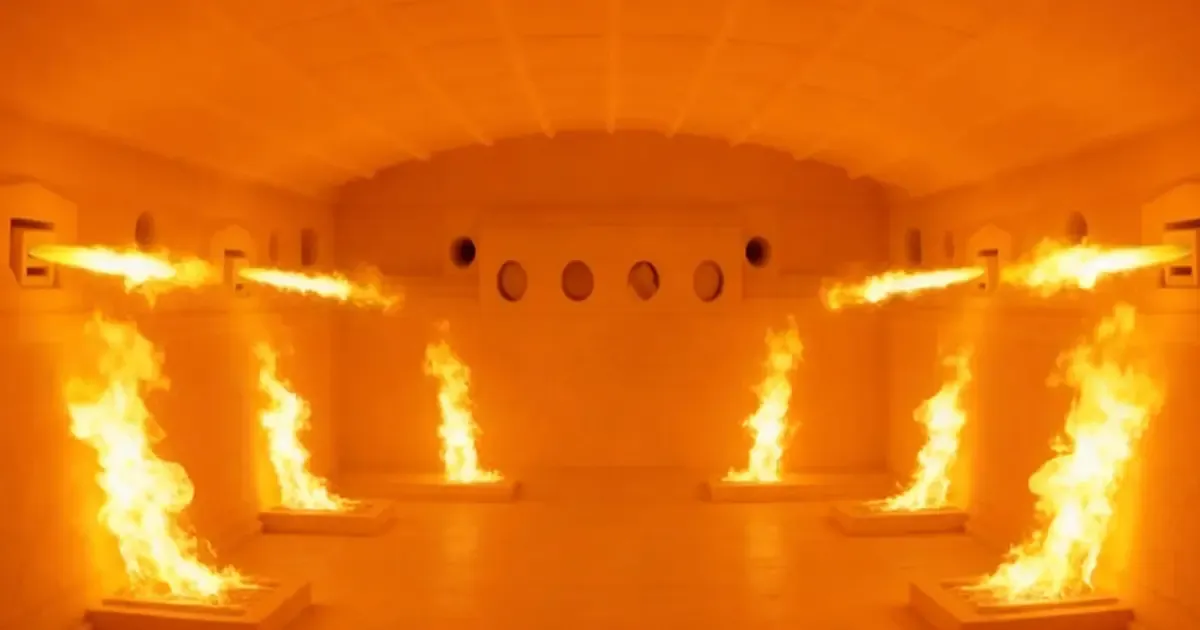
Why Furnace Lining Selection Is a Zonal Problem, Not a Fibre Brand Choice
In ultra-high-temperature furnace engineering, the wrong question is “which fibre is best?” The right question is “which zone should each material serve?” A furnace lining is a graded system: the hot face carries flame radiation, chemical attack, and mechanical load; the transition layer cuts heat flux; the backup layer controls cold-face temperature and maintenance access. Alumina wool, mullite / polycrystalline wool (PCW), and alkaline earth silicate (AES) wool each have a valid place, but only when the local temperature and chemistry place them inside their qualified range. For procurement teams, the real choice is usually alumina wool at the hot face and AES wool backup insulation in the cooled zones.
The practical rule is simple: if the hot-face temperature is above the AES continuous-service ceiling, the hot face must be an alumina-family or qualified dense refractory system. AES can only enter where the thermal profile has cooled into its safe band. This single boundary prevents most over-temperature failures, premature shrinkage, and uncontrolled devitrification in high temperature furnace insulation projects.
The 1200 °C Rule That Prevents Over-Temperature Failures
AES wool is generally qualified for continuous service up to about 1200 °C, with selected grades extending toward 1300 °C when the atmosphere, density, and anchorage are favourable. Above that band, the fibre begins to devitrify and shrink. The result is not merely a loss of insulation value; it can become a brittle, dusty layer that accelerates hot-face failure. For any zone expected to exceed roughly 1200 °C continuously, the default material family must shift to alumina refractory fibre, mullite, or PCW.
This boundary is the first gate. Every other decision—product form, density, anchor spacing, and sealing—comes after it.
What This Page Will and Will Not Claim
This page explains how to allocate materials across furnace zones. It does not rank suppliers, guarantee a specific temperature for every product, or claim that any single fibre is “safe” regardless of duty. All temperature figures are screening inputs. The final specification must be confirmed against the supplier’s technical data sheet (TDS), the project thermal profile, and, where necessary, coupon or field testing.
Material Families: Alumina, Mullite/PCW, and AES
Understanding the chemistry is the starting point. Product form, density, and installation quality define the limit.
Alumina-Based RCF: A Composition Range, Not a Universal 52 % Rule
High-alumina refractory ceramic fibre (RCF) is an amorphous alumina-silica material in which the Al₂O₃ content is raised above standard RCF grades. A commonly cited commercial example sits near 52 % Al₂O₃ with a classification temperature around 1425–1500 °C. That example is useful, but it is not a global definition of the category. Different producers use different Al₂O₃ ranges, zirconia additions (often described as zirconia insulation additions), impurity limits, and forming routes.
For procurement, the important fields are the full oxide analysis, the fibre diameter distribution, the shot or unfiberized content, the density, and the test basis for every claimed value. Alumina wool is the right starting point for hot-face zones above the AES limit, but the exact grade must be matched to the duty. For severe atmospheres, some alumina wool grades are modified with zirconia insulation stabilizers; the ZrO₂ content and its qualified atmosphere must still be verified. See how the alumina-zirconia ultra-high-temperature tier fits above 1500 °C.
Mullite, PCW, and Ceramic Fiber Modules Are Not Synonyms
- Mullite refers to the crystalline phase near 3Al₂O₃·2SiO₂.
- PCW (polycrystalline wool) normally describes sol-gel-derived crystalline fibres with a high alumina content, often applied above 1300 °C.
- A ceramic fiber module is a product geometry—folded or stitched blanket on an anchor system—not a chemistry.
A mullite fiber module or ceramic fiber module may be PCW-based, or it may use another high-alumina system. The specification should name the fibre chemistry, crystalline phase, forming route, and component form. Learn more about the PCW family in Polycrystalline Wool Fiber vs Standard Ceramic Fiber. For the highest-temperature zones, PCW / mullite modules from suppliers such as Rosetex Wool’s polycrystalline-mullite-fiberboard line are engineered for 1600–1900 °C service when the grade and atmosphere are qualified. Module installation details are covered in Polycrystalline Fiber Modules: Spec, Installation & Applications.
AES: Alkaline Earth Silicate Wool and Its Correct Service Boundary
AES wool is a CaO–MgO–SiO₂ man-made vitreous fibre. It is also supplied as bio soluble ceramic fiber or bio-soluble ceramic fiber. Its chemistry is fundamentally different from alumina-silicate systems, which is why the same selection logic cannot be used. Representative compositions show silica of 50–82 wt % and CaO + MgO of 18–43 wt %, with alumina and other minor oxides below 6 wt %.
This composition explains why AES should not be selected by Al₂O₃ content. Its value is in lower-temperature zones, backup layers, personnel-access areas, gaskets, expansion joints, and removable covers—locations where the local temperature stays within the supplier’s qualified continuous-service range. AES wool backup insulation is a valid engineering choice, but only after the thermal gradient has been verified. For the full temperature tier map, see High-Temperature Insulation Wool: Temperature Ratings & How to Choose.
Temperature and Chemistry: The Two Non-Negotiable Gates
A furnace lining fails when either temperature or chemistry is underestimated. The two interact, and either can move the safe limit well below the nominal classification temperature.
Continuous Service, Classification, and Reheat Limits Must Not Be Mixed
- Classification temperature is a laboratory reheat value, often measured over 24 hours.
- Continuous service temperature is the steady-state operating limit the supplier qualifies for a specific grade.
- Reheat change limit is the allowable permanent linear change at a stated temperature and time.
A 1600 °C classification does not mean the material can carry 1600 °C continuously in a reducing, alkali-laden, high-velocity environment. Procurement should require the continuous service temperature under the project atmosphere and the permanent linear change under the same conditions. Always state the continuous service temperature in the RFQ so suppliers cannot hide behind a single classification figure.
How Atmosphere and Contaminants Move the Real Limit Downward
High hot-face temperatures accelerate fibre devitrification and creep. Alkali vapours (Na₂O, K₂O), halides (Cl, F), sulfur compounds, heavy-metal vapours, and slag dust can all drop the safe limit. In glass and cement kilns, alkali attack is often the controlling factor. In waste incinerators, chlorides and fluorides form low-melting phases. In petrochemical heaters, sulfur and vanadium can alter refractory chemistry. The material family tells you where to start; project-specific testing tells you where to stop.
Process-by-Process Application Matrix
The same material family performs differently in different furnaces. The matrix below maps representative hot-face bands to material choices and AES entry rules for common kiln lining and furnace lining projects in high temperature furnace insulation. For a furnace-specific material comparison, see Ceramic Fiber vs Rock Wool for Furnace Linings.
| Process | Representative hot-face band | Preferred hot-face system | AES permission and location | Primary risks |
|---|---|---|---|---|
| Ceramic shuttle / tunnel kiln | 1200–1400 °C | High-alumina RCF or PCW / mullite module | Backup or lower-temperature zones after gradient verification | Thermal cycling, dust, glaze alkali |
| Glass melting furnace | 1500–1600 °C | Dense refractory plus qualified high-temperature insulation | Deep backup only; exclude vapour-exposed hot face | Alkali / halide vapour, corrosion |
| Steel reheating / soaking furnace | 1100–1300 °C | High-alumina RCF, PCW / mullite, or dense shapes | Cooler backup, doors, and joints | Scale, gas velocity, atmosphere shifts |
| Cement rotary kiln | 1400–1450 °C | Dense alumina-mullite or chemistry-specific refractory | Not at the hot face; only outer or protected backup | Alkali, dust, load, rotation |
| Petrochemical heater | 800–1000 °C+ | High-temperature RCF, PCW / mullite, or dense shapes | Convection / backup only, subject to TDS confirmation | Hydrocarbon, sulfur, thermal shock |
| Waste incinerator | 1100–1200 °C | Corrosion- and wear-specific hot-face refractory | Protected, cooler backup only | Cl / F / alkali / metal condensates |
Ceramic Shuttle and Tunnel Kilns
Ceramic kilns fire in oxidizing atmospheres with repeated thermal cycling. Representative firing zones run from about 1200 °C to 1400 °C. For the crown, roof, or wall exposed to the firing atmosphere, the starting point is a high-alumina or mullite polycrystalline fiber system selected against the peak hot-face temperature. AES wool blanket or board can sit in the backup once the interface temperature is proven to stay below its limit. The main risks are thermal cycling, airflow, abrasive dust, flame impingement, and alkali from glazes and raw materials.
Glass Melting Furnaces
Glass melting is one of the most aggressive environments. Crown, breastwall, and port zones may exceed 1500 °C and are exposed to volatile Na₂O, K₂O, boron compounds, and halides. AES should not be positioned as the hot-face insulation here. The hot-face system should be selected from high-temperature aluminosilicate, mullite, AZS, fused-cast, or other qualified glass-contact and vapour-zone refractories. AES may enter only in a deep, well-sealed backup layer after vapour penetration, condensate chemistry, and interface temperature have all been confirmed.
Steel Reheating and Soaking Furnaces
Reheating and soaking furnaces typically operate around 1100–1300 °C, with localized oxidation, CO fluctuations, scale dust, and high-velocity combustion gases. For walls, roofs, and doors directly exposed to the furnace atmosphere, alumina refractory fibre or PCW / mullite is more appropriate than AES. AES is suitable for cooler backup layers, external piping, door interiors where the gradient permits, maintenance-access areas, and expansion joints.
Cement Rotary Kilns
The cement burning zone runs near 1400–1450 °C with strong alkali and clinker dust. This is a dense-refractory-dominated environment. Alumina-mullite, magnesia-spinel, or other chemistry-specific bricks and monolithics should be selected against kiln atmosphere, coating stability, mechanical load, and thermal cycling. AES is not appropriate for the hot face. See our cement kiln thermal protection guide for a deeper case study. Fibrous insulation may be used in an outer lining or behind a dense working lining where thermomechanical design and interface temperature allow.
Petrochemical Heaters
Petrochemical heater radiant sections expose tube supports, walls, and shields to high heat. The brief lists 800–1000 °C at the tube surface, but radiant-facing surfaces can be hotter. The specification must distinguish between the process-fluid temperature, the tube-skin temperature, and the refractory hot-face temperature. See the petrochemical reformer furnace reline case study for a field example. High-alumina RCF, PCW / mullite, and dense shapes are candidates for high-temperature radiation-section components. AES is credible only in cooler convection sections, pipe covers, expansion joints, or backup zones, and only after the supplier confirms hydrocarbon, sulfur, steam, and thermal-cycling compatibility.
Waste Incinerators
Waste incinerators can contain Cl, F, alkali metals, sulfur, and heavy-metal vapours. The primary lining must be selected against the corrosion mechanism and mechanical wear. AES may be used in a cooler, protected backup zone. It should not be treated as a universal corrosive-environment replacement for RCF or PCW.
Graded Lining Architecture: Hot Face → Transition → Backup
A reliable kiln lining or furnace lining is normally arranged as a graded lining temperature gradient:
- Hot-face layer: carries flame radiation, process temperature, chemical attack, erosion, and mechanical loading.
- Transition or high-temperature insulation layer: reduces heat flux and bridges the gap between the hot-face material and cooler insulation.
- Backup or safety layer: provides most of the cold-face temperature control and may improve maintainability.
For example, a 1350–1450 °C furnace might combine a high-alumina or mullite hot-face ceramic fiber module with a high-alumina blanket or board transition and an AES backup insulation board or blanket. This graded lining stack is only an illustration. The actual transition point must come from thermal modelling and supplier data. For board specifications up to 1900 °C, see Polycrystalline Mullite Board: Ultra-High-Temp 1900 °C.
When AES Enters the System
Before selecting AES for any layer, the engineer should:
- Establish the maximum and typical hot-face temperature.
- Determine the local gas and refractory temperatures at each interface.
- Model steady-state and relevant transient conditions.
- Add margins for hot spots, nonuniform heating, process upsets, and anchorage conduction.
- Compare the calculated AES surface temperature with the supplier’s continuous-service rating for the exact grade.
- Document the basis, including atmosphere, thickness, density, facing, and fixing method.
If the interface temperature is unknown, AES should not be selected by subtracting a generic “200 °C per layer” rule of thumb.
Product Form Follows Duty, Not Generic Material Family
| Product form | Preferred duty | Key limitation |
|---|---|---|
| Module | Large roofs and walls; precompressed anchorage | Anchor design and module alignment are critical |
| Blanket | Complex shapes, wraps, and infill | Compression and erosion control must be specified |
| Board or rigid panel | Burners, doors, and seals requiring shape retention | Edge erosion and thermal-shock design require verification |
| Paper or felt | Gaskets and thin seals | Not a structural hot-face substitute |
| Dense castable, brick, or preform | High-wear or chemical-attack zones | Often the correct primary hot-face material where fibrous insulation is insufficient |
Module density does not automatically prove hot-face suitability. A ceramic fiber module and a mullite fiber module may look identical on the outside yet differ in fibre grade, density, and anchor layout. A low-density AES product may be ideal for insulation but unsuitable for direct flame, abrasion, or high gas velocity.
Failure Mechanisms: Devitrification, Shrinkage, Creep, and Chemical Attack
The real service limits are not the classification temperatures; they are the long-term changes in the material under project conditions. For an overview of all refractory families, see Refractory Insulation Materials: Types, Ratings & Applications.
Devitrification Turns Insulation into a Brittle, Dusty Layer
Amorphous RCF and AES can devitrify after prolonged high-temperature exposure, forming cristobalite and other crystalline silica species. This increases brittleness, promotes fibre breakage, and changes thermal and mechanical behaviour. The possibility that RCF can form cristobalite is not proof that every installation will do so at the same temperature or rate. Time, temperature, atmosphere, and composition all affect the process. This is why high temperature furnace insulation procurement should require a permanent linear change test under the actual service condition, not merely at a classification temperature.
Mullite and PCW Delay, but Do Not Eliminate, Degradation
PCW is crystalline rather than glassy and is generally applied above 1300 °C. That does not make it immune to grain growth, strength loss, creep, shrinkage, chemical attack, or mechanical damage. For mullite fiber module and mullite polycrystalline fiber systems above 1300 °C, the specification should require phase and grain analysis, permanent linear change, high-temperature compressive creep or stress-strain data where applicable, thermal-cycling resistance, and chemical exposure data.
Alkalis and Halides Can Move the Failure Boundary Below the Nominal Temperature
In glass and cement environments, alkali vapour can attack aluminosilicate and mullite materials. In incinerators and some petrochemical heaters, chlorides, fluorides, sulfur, and heavy-metal vapours can create low-melting phases, deposits, or corrosive penetration. AES’s Ca/Mg/Si chemistry should not be assumed to resist these environments better than alumina. The final selection requires either published environment-specific test data, a laboratory crucible or coupon test, or a controlled field trial.
Load, Creep, and Anchorage Are Part of the Material Specification
A fibre that performs well as a free blanket may fail under compressive load, hanging-module weight, thermal gradient stress, or vibration. For roofs and vertical walls, the anchor material, anchor spacing, cold-face washer, expansion allowance, and module compression are as important as the fibre chemistry. For floors and hearths, fibrous insulation often requires a dense wear course. The material should be selected for the combined temperature and load, not for temperature alone.
Procurement Specification and Supplier Evaluation Checklist
A generic RFQ requesting “AES” or “high-alumina fibre” invites incompatible offers. A robust procurement specification replaces brand comparison with test-backed data. The minimum fields are listed below.
1. Process and Equipment
- Furnace or kiln type
- Hot zone and dimensions
- New installation or repair
- Existing lining and failure history
2. Temperature
- Peak and continuous hot-face temperature
- Temperature at each interface
- Heating and cooling rates
- Cycle frequency and duration
3. Atmosphere and Chemistry
- Oxidizing, reducing, or mixed atmosphere
- Fuel and air/fuel ratio
- Alkali, halide, sulfur, metal, or slag species
- Condensate, dust, and deposit chemistry
4. Mechanical Duty
- Gas velocity
- Abrasion or particle impingement
- Load and orientation
- Vibration and thermal shock
5. Product Requirements
- Blanket, board, module, paper, or rigid form
- Thickness, density, and dimensions
- Fibre orientation and surface treatment
- Binder, organic content, and outgassing limits
6. Performance Evidence
- Classified, continuous, and allowable service temperatures
- Thermal conductivity curve
- Permanent linear change
- Shrinkage and density after exposure
- Compressive creep and modulus data where relevant
- Chemical resistance and devitrification data
7. Installation and QA
- Anchorage system and spacing
- Expansion-joint design
- Drawings, installation sequence, and curing procedure
- Witness samples and lot traceability
8. Health, Safety, and Compliance
- Safety data sheet and jurisdiction-specific classification
- Fibre-diameter and biopersistence data where relevant
- Personal protective equipment and ventilation requirements
- Cutting, removal, and disposal instructions
Supplier Comparison Must Use One Validated Test Basis
Suppliers should complete a single technical data matrix. Reject comparisons based on incompatible temperature definitions, different test durations, different atmosphere conditions, unspecified shot content, unspecified density, or nominal “use temperatures” without a test basis. The matrix should include chemical composition, phase and microstructure, density and dimensions, temperature-specific thermal conductivity, permanent linear change with time and temperature, binder content and loss on ignition, fibre diameter distribution, shot content, packaging with lot traceability, current safety and transport documents, and the installation warranty scope.
Installation, Commissioning, Inspection, and Maintenance
Design performance depends on execution. A small but systematic installation defect can cause more damage than a modest difference in nominal fibre grade.
Installation Quality Controls the Real Service Temperature
Installation should follow the supplier’s current instructions and applicable project safety rules. A robust procedure includes cleaning and inspecting the shell, verifying anchor weld quality and layout, keeping ceramic fiber module layers and blankets dry before installation, maintaining designed compression, offsetting joints, avoiding gaps at kiln lining terminations and penetrations, sealing around burners, thermocouples, tubes, and doors, and recording lifts, serial numbers, and as-built photographs.
Pre-Commissioning and Commissioning Should Be Acceptance Milestones
Before heating, the purchaser should confirm dimensions and thickness, density, joint alignment, anchor torque or weld integrity, expansion gaps, vapour seals, moisture removal pathway, and compatibility of coatings and adhesives. Commissioning should follow the qualified heating curve. Organic binders should be removed according to the supplier’s instructions. The first heat-up should not be treated as an opportunity to “test the maximum temperature.”
Acceptance should include an initial infrared or contact thermal survey where safe, a visual inspection after the first controlled cycle, documentation of any local overheating, measured cold-face temperatures, and confirmation that results are consistent with the design model.
Maintenance Should Be Condition-Based and Contamination-Aware
Ongoing inspection should record local thinning, shrinkage, cracking, powdering, slag penetration, deposit formation, module loss, anchor exposure, and cold-face hot spots. If the hot-face temperature rises above the design basis, the response should be to recalculate the entire gradient rather than simply adding AES. AES may be appropriate in the cooler backup, but it cannot restore a failed high-temperature face.
Bio-Solubility and Occupational Safety: Evidence, Not Marketing
AES belongs to a family designed to improve dissolution in physiological fluids relative to conventional RCF. Historical regulatory concepts describe exemptions based on alkaline/alkaline-earth oxide content and demonstrated low biopersistence. This is not a guarantee that every AES product is non-classified or harmless. Fibre diameter, length, dose, durability, and jurisdiction-specific rules can change the conclusion.
Dust Control Applies to Every Fibre Family
IARC has evaluated man-made vitreous fibres, and crystalline silica is classified as carcinogenic. Heated man-made vitreous fibres can devitrify and form cristobalite. Cutting, drilling, removing, or disturbing any of these materials can create a dust hazard. Procurement should require safety data sheets and local hazard classification, enclosure and extraction, wet methods where compatible, HEPA vacuuming rather than sweeping, personal protective equipment specified by a qualified safety professional, training for installation and demolition personnel, and residue and waste management consistent with the project jurisdiction.
Whether the material is called bio soluble ceramic fiber, bio-soluble ceramic fiber, or simply AES wool, cutting, removal, and disturbance can still generate dust. “Bio-soluble” should never be translated into “no controls required.”
Decision Framework and Common Specification Mistakes
Selection should pass through five gates before a product is named:
- Temperature gate: Is the hot face above ~1200 °C, or is there no reliable margin for AES? If yes, assign an alumina, mullite/PCW, or dense high-temperature system to the hot face.
- Chemistry gate: Are alkalis, halides, sulfur, slags, or metal vapours present? If yes, require environment-specific testing and do not infer compatibility from the material family.
- Mechanics gate: Is there erosion, load, vibration, thermal shock, or high gas velocity? If yes, add a dense or reinforced transition and verify anchorage.
- Gradient gate: Has the temperature at the AES surface been modelled and tested? If no, do not place AES adjacent to the hot face.
- Lifecycle gate: Is the zone frequently accessed, cut, repaired, or disturbed? If yes, consider bio soluble ceramic fiber or another suitable low-temperature material only in the accessible cooled zone, with a qualified maintenance plan.
Red Flags That Should Stop the AES-as-Hot-Face Assumption
| Red flag | Required action |
|---|---|
| Hot-face temperature exceeds 1200 °C | Use alumina-family or qualified high-temperature system |
| No supplier TDS for a 1300 °C claim | Reject as unproven |
| Alkali, halide, or metal vapour is present | Require chemical compatibility evidence |
| Only “classified temperature” is provided | Request continuous-service and test data |
| AES and PCW are treated as interchangeable | Separate chemistry, crystallinity, and product form |
| Module density is provided without anchor design | Require complete system specification |
| “Bio-soluble” is used as a safety absolute | Apply SDS and site HSE controls |
The Bottom Line for Procurement Teams
For ultra-high-temperature service:
- Use alumina wool and alumina-family materials for the hot-face, transition, and high-temperature insulation role.
- Use AES wool backup insulation for backup, low-temperature zones, personnel-access areas, and selected gasket or expansion-joint applications—only after the local temperature and chemistry are verified.
- Where the environment is chemically aggressive or mechanically severe, do not force a fibrous solution. Select dense refractory, zirconia insulation grades such as AZS, or other qualified materials first, then design the insulation system around them.
This allocation prevents both under-specification of the hot face and unnecessary over-specification of the entire wall. Procurement teams that enforce this discipline reduce the risk of over-temperature failure, uncontrolled devitrification, incompatible chemical exposure, and unsupported safety claims.
Related Reading
Frequently asked
Can AES replace alumina fibre at 1400 °C? +
No, not as a general rule. AES wool is generally applied up to about 1200 °C, while PCW, mullite, and alumina-family systems address zones above 1300 °C. A 1400 °C hot face requires an alumina-family or qualified dense refractory system.
Is high-alumina RCF always 52 % Al₂O₃? +
No. The 52 % Al₂O₃ figure is a documented commercial example, not a universal definition. Different producers use different alumina ranges, zirconia additions, impurity limits, and forming routes. Procurement should require a full oxide analysis and the supplier’s grade definition.
Is a PCW module the same as a mullite module? +
Not automatically. PCW describes a polycrystalline, normally high-alumina fibre family; mullite refers to a crystalline composition and phase field; a module is a component geometry. The specification must identify fibre chemistry, crystalline phase, forming route, and product form.
Is AES bio-soluble, so workers can handle it without controls? +
No. Bio-solubility relates to composition and biopersistence, but cutting, removal, and disturbance can still generate respirable dust. Site controls, PPE, ventilation, and waste management remain necessary.
Does a 1600 °C classification mean the material can carry 1600 °C continuously? +
Not without the supplier’s qualified continuous-service evidence. Atmosphere, loading, time, chemical exposure, and installation conditions must all be considered. Classification temperature, reheat temperature, and continuous service temperature are not interchangeable.
Can AES be used in a glass furnace? +
Only in a cooler, protected backup zone after alkali-vapour and interface-temperature verification. It should not replace the hot-face refractory exposed to aggressive glass-furnace chemistry.
What is the single most important field in the RFQ? +
The combination of hot-face temperature and atmosphere. Neither alone is sufficient. A high-temperature, chemically aggressive atmosphere may require a different system from a clean, oxidizing furnace at the same nominal temperature.
Request a quote
Interested in our insulation solutions? Send us your requirements and our team responds within one business day.