
Refinery & Reformer Insulation: A Unit-by-Unit Guide
Unit-by-unit refinery insulation engineering: classification vs continuous use temperature, hot-wall and cold-wall reformers, coker thermal cycling, SRU dew points, and the offshore constraint layer.
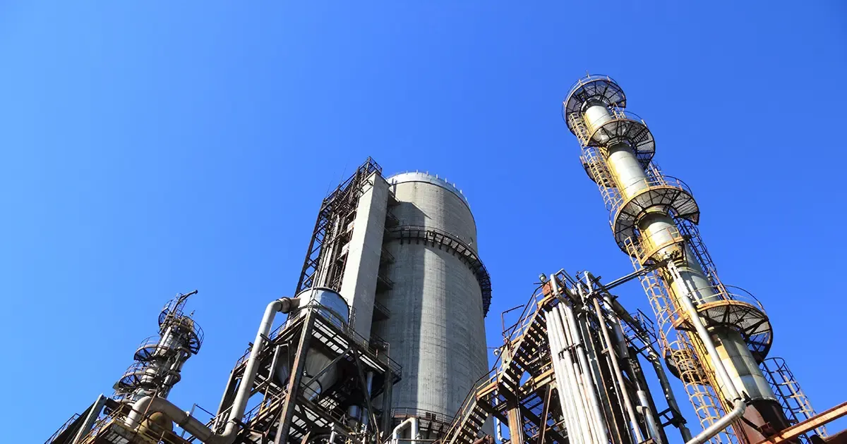
Choosing refinery insulation is not a matter of picking a material off a single temperature chart. A crude distillation column, an FCC regenerator, a delayed coker drum and a catalytic reformer furnace all run in different temperature bands, carry different process media and fail in different ways. A system that performs for years on a steam main can shrink, crack or corrode within one operating cycle on a coker drum. This guide walks through the refinery unit by unit, explains the engineering logic behind each insulation decision, and closes with the constraints that reshape offshore refinery insulation when the plant moves onto a platform.
Classification Temperature vs Continuous Use Temperature
The single most common specification error in high-temperature refinery insulation is confusing classification temperature with continuous use temperature. The classification temperature is a laboratory value: the temperature at which a material shows no more than a defined permanent linear shrinkage — typically 3–4 % after 24 hours — under ideal conditions. It is not the temperature at which the material can operate for years.
For refractory ceramic fiber, the practical margin between the two is typically 150–200 °C. A standard 1260 °C classification grade is recommended for continuous service only up to roughly 1050–1100 °C in clean oxidizing atmospheres. Zirconia grades classified at 1430 °C are rated for continuous use around 1300–1350 °C. Designing a lining to its classification temperature instead of its continuous use temperature is a leading cause of premature shrinkage, joint openings and hot spots in refinery furnaces.
| Material | Classification / grade | Continuous use | Typical forms |
|---|---|---|---|
| Ceramic fiber, standard | 1260 °C | ~1050–1100 °C | Blanket, module, board |
| Ceramic fiber, high-alumina | 1400 °C | ~1200 °C | Module, board |
| Ceramic fiber, zirconia | 1430 °C | ~1300–1350 °C | Blanket, module |
| Rock wool | — | ~650 °C | Board, blanket, pipe section |
| Calcium silicate, Type I (ASTM C533) | — | ~650 °C | Block, pipe covering |
| Calcium silicate, high-temp (ASTM C533 Type II basis) | — | ~1000 °C | Block |
| Glass wool | — | ~250 °C | Blanket, board |
| Aerogel blanket | — | −200 to +650 °C | Flexible blanket |
Keep this table within reach through the rest of the article: every unit below draws on it, and every grade above is quoted at its continuous use temperature, not its classification.
Crude and Vacuum Distillation: 150–420 °C and the Vacuum Sealing Problem
The crude distillation unit and vacuum distillation unit anchor the warm end of refinery insulation. Atmospheric columns operate from about 150 °C at the top to 420 °C at the bottom, with vacuum columns showing similar metal temperatures under sub-atmospheric pressure.
For most columns, rock wool board or calcium silicate sections with aluminum or stainless-steel jacketing are standard, and rock wool pipe sections carry the surrounding transfer lines. Two details separate this unit from ordinary warm service:
- Vacuum sealing. Any air in-leakage through poorly sealed jacketing joints can degrade vacuum performance and drive internal oxidation. On a vacuum column, the outer cladding is part of the process system, not just weather protection.
- Personnel protection governs thickness. In the cooler upper sections, insulation thickness is often set by the touch-temperature limit — keeping the outer surface at or below about 60 °C — rather than by heat loss economics.
For the wider context of how these units fit into a full plant specification, see our petrochemical plant insulation guide.
Fluid Catalytic Cracking: Erosion and the 730 °C Regenerator
The FCC unit is the most mechanically abusive environment in the refinery. Riser and reactor outlets run at 510–565 °C, while the regenerator dense bed sits at 650–730 °C, with dilute-phase and catalyst-cooler zones reaching 760 °C or higher.
The insulation strategy is layered from the inside out:
- Reactor and regenerator vessels carry an internal refractory lining — abrasion-resistant castable anchored to the shell — because catalyst fines erode any unprotected surface. Behind it sits an insulating castable or ceramic fiber module layer, with external insulation only where shell temperatures still require it.
- Cyclones and standpipes rely on refractory-lined systems for the same erosion reason.
- The main fractionator splits by temperature: a lined lower section with external rock wool or calcium silicate, and a cooler upper section where lighter materials are acceptable.
Two constraints matter for the insulation engineer. First, the reactor–regenerator pair expands thermally by different amounts, so expansion joints in both refractory and insulation are mandatory, not optional. Second, catalyst fines that penetrate a damaged jacket create hot spots and feed corrosion under insulation on the shell beneath — the same CUI mechanism found elsewhere in the plant, but accelerated by abrasive, heat-carrying particles.
Hydrotreaters and Hydrocrackers: Designing Around Hydrogen
Hydrotreating and hydrocracking reactors operate at 260–430 °C depending on feedstock — VGO units around 360–380 °C, residue units up to 400–440 °C — under high hydrogen partial pressure. Metallurgy, not insulation, is the star of this unit: reactor peak temperatures are limited to roughly 427 °C by the steel itself.
Insulation still matters in three specific ways:
- HTHA risk assessment. For piping above about 204 °C in high-pressure hydrogen service, material selection must respect the Nelson curves in API RP 941, which define where carbon and low-alloy steels become vulnerable to high-temperature hydrogen attack. Insulation does not change the metallurgy, but it determines the metal temperature profile that the curve analysis depends on.
- Temperature excursions. Hydrocracking is strongly exothermic, and a runaway can push wall temperatures far above design in minutes. The insulation system must tolerate rapid, unplanned spikes without melting, shrinking or slumping.
- Quench zones. Multiple catalyst beds with quench-gas injection create internal temperature steps; the external insulation design must follow these zones so no surface point becomes a personnel-protection problem.
Refinery insulation on this unit follows the metallurgy, not the other way round. In practice, hot reactors and high-pressure loops use calcium silicate or rock wool with stainless-steel jacketing, selected so the system neither traps hydrogen against the wall nor holds moisture there.
Catalytic Reformers: Hot-Wall vs Cold-Wall Logic
The catalytic reformer is where insulation design meets reactor metallurgy head-on. Reactor inlet temperatures run around 450–520 °C and outlets 500–550 °C, and the industry builds two completely different vessel philosophies to handle this.
Cold-wall reactors protect a carbon-steel pressure boundary with an internal refractory lining, often backed by insulating material and an internal metal liner. The shell stays below about 343 °C — comfortably within carbon-steel creep limits. The primary insulation is on the inside; the outside may need only light insulation for personnel protection. Semi-regenerative units have traditionally favored this design. Its weakness is degradation: if the internal lining develops hot spots, the shell can creep toward its limits (the creep transition for common vessel carbons sits near 399 °C), and external air cooling becomes an emergency measure.
Hot-wall reactors make the shell from Cr-Mo alloy steel — typically 1.25Cr-0.5Mo, or 2.25Cr-1Mo above 538 °C — and insulate it externally. The shell runs at or near process temperature, so external reformer insulation must limit heat loss, keep surfaces safe to touch, and avoid introducing moisture that would attack the alloy. Continuous catalytic regeneration (CCR) units use hot-wall reactors almost exclusively, either as individual vessels or stacked in one compartmented shell. Whether a given reactor is hot-wall or cold-wall decides where the reformer insulation sits, what material it is made of, and which failure mode will end its service life.
Reformer insulation also faces a chemical quirk: traces of HCl from catalyst regeneration can migrate to cooler zones and condense as acid. Reformer insulation in these transition zones must keep metal temperatures above the acid dew point — the same logic the sulfur unit below follows in its most extreme form. For what these furnaces look like from the inside, see our reformer furnace reline case study.
Reformer Furnaces and Hydrogen Plants: The Zones Above 900 °C
Whatever the reactor wall philosophy, the fired heater that feeds it runs hotter than anything else in the unit. The radiation section of a refinery furnace operates at 900–1300 °C, which places it firmly in ceramic-fiber territory — this is the heart of refinery furnace insulation: ceramic fiber modules of 1260 °C or 1400 °C grade on walls and roofs, castable refractory with anchors on floors and burner quarls, and backup insulation behind the hot face to hold shell temperatures down.
Steam methane reformers in hydrogen plants push this further. Reformer tubes exit at 820–950 °C, tube skin temperatures approach 980 °C, and the transfer pigtails and manifolds need high-nickel alloys to survive. External insulation on this piping is typically ceramic fiber blanket or modules, and personnel protection becomes a primary design driver — few places in the plant are less forgiving of a thin or damaged jacket.
The convection section, where flue gas cools to 400–650 °C, transitions back to rock wool or calcium silicate on ducting and waste-heat coils. Getting this transition right — ceramic where the gas is hot, mineral wool where it is not — is what separates refinery furnace insulation that lasts from insulation that cooks.
Delayed Cokers: Heat, Water and Mechanical Abuse
The delayed coker drum may be the hardest vessel in the refinery to insulate well. Feed enters at 460–500 °C, and every 12–24 hour cycle ends with the drum quenched with water to near ambient before coke is cut out with high-pressure jets. Heat, water and mechanical abuse — the three enemies of any insulation system — arrive in the same shift, and a blanket chosen by classification temperature alone will not survive its first year.
Traditional fibrous insulation struggles here: binder-containing blankets age rapidly above their binder burnout limits during the heating phase, then soak up quench water during the cooling phase, setting up severe corrosion under insulation — a point our companion article on rock wool in refining develops further. Modern practice therefore favors:
- Flexible, binder-free systems — ceramic fiber blanket or aerogel blanket — that tolerate thermal shock and dry out without structural damage.
- Robust metal jacketing with sealed seams, because hydraulic decoking guarantees water exposure.
- Removable insulation covers on manways and top and bottom heads, which see frequent inspection.
Thermal fatigue is the structural counterpart: the skirt-to-cone junction is a well-known cracking location, and any rigid insulation that restrains shell movement accelerates the damage. Flexible systems with expansion provisions are the default recommendation.
Sulfur Recovery: When Insulation Thickness Controls Corrosion
The Claus sulfur recovery unit spans the widest temperature range of any refinery unit: the thermal reactor burns at 1000–1400 °C behind dense refractory, catalytic reactors run at 250–350 °C, and condensers sit at 130–160 °C. Refinery insulation on this unit is not primarily an energy decision — it is a corrosion-control decision.
Two dew points govern everything:
- Sulfur dew point. Process gas in the catalytic stages must stay at least about 17 °C above the sulfur dew point, or liquid sulfur condenses in the catalyst pores and deactivates the bed. Undersized insulation on a reactor outlet can quietly kill conversion.
- Acid dew point. In tail-gas sections, SO₃ and water vapor can raise the acid dew point to as high as 177 °C. If insulation on tail-gas piping or waste-heat equipment lets the wall fall below this, concentrated sulfuric acid condenses on the metal and corrosion becomes rapid and visible within months.
The countermeasure is calculated insulation thickness — sometimes deliberately combined with steam tracing — so the wall temperature sits safely above both thresholds. Calcium silicate pipe insulation with stainless jacketing is the workhorse here, chosen precisely because its compressive strength and known thermal performance keep wall temperatures predictable over years.
Amine Units and Flare Stacks: The Quiet Extremes
Two units sit at the edges of the refinery insulation map and are easy to get wrong by over- or under-thinking them.
Amine treating is thermally simple — absorbers at 40–65 °C, regenerators at 120–130 °C, reboilers at 150–175 °C — and glass wool board or rock wool blanket covers most of it. The watch item is wet insulation: amine degradation products cause localized internal corrosion, and if the insulation system also allows external corrosion, wall loss accelerates from two directions at once. CUI prevention, not temperature rating, is the real specification task.
Flare stacks face the opposite profile in refinery insulation terms: intermittent service, flame temperatures above 1200 °C, and radiant heating of a structure that may sit cold and rain-soaked for months. The lower radiant section typically carries refractory lining; upper sections may need only ceramic fiber blanket where wall temperatures demand it. The dominant failure mode is thermal shock — sudden ignition of a cold, wet stack cracks rigid refractory — so the lining system must be detailed for rapid heating, not just peak temperature.
Offshore Refinery Insulation: The Extra Constraint Layer
Everything above applies to an onshore refinery. An offshore platform keeps every one of those requirements and adds a layer of its own, which is why offshore refinery insulation deserves its own specification logic rather than a footnote.
- Marine atmosphere. Salt spray destroys bare aluminum jacketing through pitting and galvanic attack, so offshore specifications call for stainless-steel or coated-aluminum cladding — commonly a 0.5 mm stainless minimum in exposed areas under NORSOK M-004 (the current designation of the former R-004), the governing North Sea standard for thermal, acoustic and fire insulation on topsides.
- Weight limits. Deck loading is budgeted in kilograms per square metre, and thick dense insulation on large bore piping consumes that budget fast. The permissible thickness may be set by structural engineers, not thermal calculations — which is exactly where lightweight aerogel blanket earns its keep, delivering high thermal resistance at a fraction of the weight of rigid materials.
- Fire ratings. Offshore design distinguishes hydrocarbon pool fire ratings (H-ratings) from jet fire ratings (J-ratings) under the project fire-response strategy, aligned with ISO 13702. Thermal insulation and passive fire protection are separate duties: process piping in fire zones may need PFP wrap over insulation, emergency shutdown valves need dedicated fire-rated jackets, and structural steel under pressurized equipment needs PFP regardless of process temperature.
- Amplified CUI. Constant humidity, salt-laden air, daily temperature cycling and cramped inspection access make corrosion under insulation the dominant maintenance cost offshore — our companion guide to marine and offshore fire insulation standards covers the material side. API RP 583 frames the management program: hydrophobic insulation materials, sealed jacketing seams, drain points at low spots, and inspection priority on systems whose operating temperature cycles through the CUI-critical band, roughly −4 to +121 °C.
- Modular construction. Topsides are insulated onshore as modules, transported by barge and lifted into place. The insulation must survive transport loads, salt exposure and partial removal for weld inspection — which strongly favors removable covers and blanket systems over rigid sections that shatter when disturbed.
When Insulation Fails: Dew Points, Cycling and Access
Step back from the unit list and three failure families explain most refinery insulation problems.
Dew-point failures are the quiet ones. Whether it is sulfuric acid on SRU tail gas, HCl near a reformer regeneration loop, or plain condensation under a jacket, the mechanism is the same: a wall temperature allowed to fall below a local dew point. The fix is rarely "more insulation" — it is correctly calculated insulation, sometimes with tracing, that holds the wall above the threshold.
Cycling failures are the mechanical ones. Coker drums, regenerators and transfer lines expand and contract daily; rigid materials crack, anchors fatigue, and joints open. Flexible blanket systems with expansion provisions tolerate this movement, which is why they dominate cycling service — provided their continuous use temperature genuinely covers the peak, not just the nameplate grade.
Access failures are economic. Valves, flanges, manways, turbines and compressors need regular attention, and permanent insulation destroyed at each turnaround becomes a recurring cost. Removable insulation covers — flexible jackets with straps or fasteners — survive multiple turnaround cycles, cut critical-path downtime and open the surface for inspection without cutting metal. With refinery turnarounds running every 3–6 years, and offshore man-hour rates at their premium, removable covers frequently pay back within a single maintenance cycle.
Material Temperature Limits at a Glance
The table below consolidates the working limits used throughout this guide. Densities are typical commercial ranges; thermal conductivity varies with mean temperature, so economic-thickness calculations should always use manufacturer k-value curves rather than single-point values. When a datasheet is ambiguous, ask the supplier to state the continuous use temperature at your design conditions, in writing.
| Material | Continuous service | Typical density | Refinery roles |
|---|---|---|---|
| Glass wool | ~250 °C | 10–48 kg/m³ | Low-temp piping, amine units, acoustics |
| Rock wool board / blanket | ~650 °C | 80–200 kg/m³ | Vessels, columns, furnace backup |
| Rock wool pipe sections | ~650 °C | 120–180 kg/m³ | Process piping, steam mains |
| Calcium silicate, Type I | ~650 °C | 170–240 kg/m³ | Hot piping, reboilers, SRU service |
| Calcium silicate, high-temp | ~1000 °C | 200–270 kg/m³ | Furnace-adjacent equipment |
| Ceramic fiber blanket (1260 grade) | ~1050–1100 °C | 64–160 kg/m³ | Furnace linings, reformer backup |
| Ceramic fiber module (1400 grade) | ~1200 °C | 200–320 kg/m³ | Furnace roofs and walls |
| Ceramic fiber, zirconia (1430 grade) | ~1300–1350 °C | 128–160 kg/m³ | Hottest furnace zones |
| Aerogel blanket | −200 to +650 °C | 180–220 kg/m³ | CUI mitigation, weight-limited offshore work |
| Cellular glass | −260 to +400 °C | 110–150 kg/m³ | Cryogenic and low-temp hydrocarbon service |
Specifying Refinery Insulation: What to Put in an Enquiry
Most specification errors we see trace back to information that was missing at enquiry stage, not to the material choice itself. A complete refinery insulation enquiry states:
- The unit and the service — "hydrotreater reactor loop, 410 °C, high-pressure hydrogen" tells us more than a bare temperature.
- Design and operating temperatures, including excursion expectations for cycling units.
- Line sizes and geometry, since standard bore sizes take preformed sections while large or irregular geometry takes blankets — the construction-level question of refinery insulation types is covered separately in our industrial pipe insulation types guide.
- Ambient and jacketing requirements — indoor, coastal, or full offshore refinery insulation service with stainless cladding.
- CUI policy — hydrophobic materials, sealed seams, drain details.
- Access points — valves, instruments and manways that justify removable insulation covers.
- Applicable standards — ASTM material standards, API recommended practices, and project fire strategy.
Send those seven lines and the material shortlist effectively writes itself. Where a unit sits above 1000 °C, the answer will start with ceramic fiber; between 250 and 650 °C it will start with rock wool and calcium silicate; below 250 °C, glass wool and aerogel take over. The unit-by-unit logic above is what turns those bands into a specification that survives its first turnaround.
Frequently asked
What is the difference between classification temperature and continuous use temperature? +
Classification temperature is a laboratory rating: the temperature at which a material shows no more than a defined permanent linear shrinkage, typically 3–4 % after 24 hours. Continuous use temperature is what the material can withstand for years in service. For ceramic fiber the practical margin between the two is 150–200 °C — a 1260 °C classification grade is good for roughly 1050–1100 °C continuous in clean oxidizing atmospheres. Specifying to the classification figure instead of the continuous use temperature is the most common cause of premature lining shrinkage and hot spots.
Why do catalytic reformer reactors come in hot-wall and cold-wall designs? +
A cold-wall reactor protects a carbon-steel shell with an internal refractory lining, keeping the metal below about 343 °C; the insulation lives on the inside, and the shell needs only light external cover. A hot-wall reactor is made from Cr-Mo alloy and runs at process temperature, so it is insulated externally like any hot pipe. Semi-regenerative units have traditionally used cold-wall vessels, while continuous catalytic regeneration (CCR) units are invariably hot-wall. The choice decides where the insulation sits, what material it is made of, and which failure mode will end its service life.
What insulation survives a delayed coker drum? +
Coker drums cycle from about 460–500 °C down to a water quench every 12–24 hours, so the insulation sees heat, water and mechanical abuse in the same shift. Flexible, binder-free systems — ceramic fiber blanket or aerogel blanket — tolerate the thermal shock and dry out without structural damage, protected by well-sealed metal jacketing against quench water. Rigid materials crack under the cycling, and any system that restrains shell movement accelerates the known fatigue cracking at the skirt-to-cone junction. Removable covers on manways and heads handle the frequent inspection access.
Why does insulation thickness control corrosion in a sulfur recovery unit? +
Because two dew points govern the unit. In the catalytic stages, process gas must stay at least about 17 °C above the sulfur dew point or liquid sulfur condenses in the catalyst pores and deactivates the bed. In tail-gas sections, SO₃ and water can raise the acid dew point to as high as 177 °C — if the wall temperature falls below that, concentrated sulfuric acid condenses on the metal and corrosion becomes rapid. Correctly calculated insulation thickness, sometimes with steam tracing, is what holds wall temperatures above both thresholds; 'more insulation' is not automatically the answer.
What is different about offshore refinery insulation? +
An offshore platform keeps every onshore requirement and adds its own layer. Salt spray rules out bare aluminum jacketing in favour of stainless or coated aluminum, commonly 0.5 mm stainless minimum under NORSOK M-004. Deck loading in kilograms per square metre can cap insulation thickness regardless of the thermal calculation, which favors lightweight aerogel blanket. Fire strategy adds hydrocarbon pool-fire and jet-fire ratings on top of thermal duty. Humidity, salt and temperature cycling amplify corrosion under insulation, and modular construction favors removable, blanket-based systems that survive transport and partial removal for weld inspection.
Which insulation should I use for refinery piping at around 600 °C? +
At 600 °C the natural starting point is rock wool pipe sections or calcium silicate, both rated for continuous service at about 650 °C. Rock wool sections at 120–180 kg/m³ are the standard answer for process piping and steam mains; calcium silicate brings higher compressive strength where jacketing loads or foot traffic demand it. The material must be paired with the right jacketing and sealed seams, because at this temperature a wet insulation system is simultaneously a heat-loss problem and a corrosion problem. Above roughly 650 °C the answer moves to ceramic fiber products.
How often should refinery insulation systems be inspected? +
Inspection should follow the operating temperature, not the calendar alone. Systems cycling through the corrosion-under-insulation critical band — roughly −4 to +121 °C, peaking around 60–80 °C where condensation is most active — deserve priority inspection at every opportunity, as framed by API RP 583. jacketed systems on dew-point-critical service such as SRU tail gas need wall-temperature verification whenever the unit is opened. Between turnarounds, which typically run every 3–6 years, thermography and jacketing seam surveys catch damaged cladding before it becomes a CUI repair job.
Request a quote
Interested in our insulation solutions? Send us your requirements and our team responds within one business day.