
Cement Kiln & Rotary Furnace Refractory Lining Selection
Zone-by-zone refractory lining selection for cement kilns and rotary furnaces, with clear boundaries for ceramic fiber and calcium silicate roles in backup insulation.
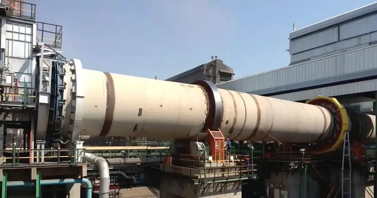
Selecting a refractory lining for a cement kiln or rotary furnace is not a single-temperature decision. A rotating shell imposes conditions no static furnace sees: continuous mechanical flexing (shell ovality), abrasive material charge, coating that builds up and breaks away, and an axial temperature and chemistry gradient running from the feed end to the discharge. This guide breaks the kiln into its operating zones, explains which refractory roles each zone demands, and — critically for insulation buyers — clarifies where ceramic fiber and calcium silicate belong (and where they do not).
Why a Rotary Kiln Lining Is Different from a Static Furnace
In a static furnace, a lining can often be designed around temperature and atmosphere alone. In a rotary kiln, the lining is a rotating structural ring. Three loads act on it simultaneously:
- Thermal load — flame radiation, hot gas convection, and conduction through coating, brick, and shell.
- Mechanical load — the charge rolls and slides across the lining with every revolution; the shell deforms elliptically between tyres, putting the brick ring under cyclic compression and shear.
- Chemical load — alkalis, sulfur, and chlorides volatilize in the hot zone, travel with the gas stream, condense in cooler zones, and re-enter the bed with the feed. This internal circulation concentrates salts at brick joints and pores.
A lining chosen on classification temperature alone ignores two of these three loads — which is why like-for-temperature substitutions so often fail early.
Lining Zones Along the Kiln Axis
Modern dry-process cement kilns are lined zone by zone. Each zone pairs a characteristic temperature range with a dominant failure mechanism, and the working-layer choice follows from that pairing:
| Zone | Typical process temperature | Dominant stresses | Working-layer direction |
|---|---|---|---|
| Kiln inlet / preheating | 800–1200 °C | Alkali, sulfur, chloride condensation; coating build-up | Dense alkali-resistant brick or abrasion-resistant high-alumina brick |
| Upper transition | 1200–1350 °C | Coating formation and loss; thermal cycling; salt deposition | Magnesia-alumina spinel or toughened high-alumina brick |
| Sintering (clinkering) | 1400–1500 °C | Clinker liquid-phase infiltration; coating stability | Basic brick (magnesia-spinel or dolomite) that takes a stable clinker coating |
| Lower transition | 1250–1400 °C | Temperature drop, clinker abrasion, local coating instability | Spinel or wear-resistant high-alumina brick |
| Cooling zone / kiln discharge | 1100–1300 °C | Quench, falling clinker impact, secondary-air disturbance | Wear-resistant brick, or steel-fiber-reinforced castable precast shapes at the nose |
Two engineering facts are worth remembering when arguing for lining investment: industry studies of large kilns report shell surface temperatures of roughly 350–400 °C in the transition and sintering zones, with associated heat losses on the order of 8–15% of total heat input in poorly maintained sections. The first energy-saving move is not adding insulation — it is restoring the hot-face lining and a stable clinker coating.
The Rule That Matters Most: Working Layer and Insulation Layer Do Not Swap
The single most common specification error we see in rotary furnace enquiries is treating a high classification temperature as permission to use a soft insulation product on the hot face. It is not. Refractory linings work as a layered system:
- The working layer (dense brick, castable, or precast shapes) takes the flame, the charge, and the chemistry. It carries mechanical load and forms the structural face.
- The insulation layer (ceramic fiber, calcium silicate, insulating firebrick) sits behind the working layer in suitable locations, reducing heat flow to the shell. It must never be placed where the charge rolls, where flame impinges, or where salts condense.
Ceramic fiber products (blanket, board, folded modules) bring low thermal conductivity, low heat storage, and fast heat-up — ideal for the static ancillary equipment around the kiln: kiln hood, smoke chamber, tertiary air duct, preheater vessels, and repair doors. In these stationary enclosures, fiber modules anchored to the steelwork cut heat storage and shorten startup cycles. They are not used as the load-bearing lining of the rotating barrel itself: continuous rotation, charge shear, and vibration will compact, shed, and destroy an unprotected fiber hot face. Our ceramic fiber module product page covers anchor systems and module formats for static furnace linings.
Calcium silicate board is the complementary cold-face material: rigid, dimensionally stable, machinable, and strong in compression — well suited as a hard backup behind dense working layers in static equipment, and as protective pack-off material around nozzles and openings. Grades are specified per recognized standards such as ASTM C533 or EN 14306, with standard grades serviceable to about 650 °C and high-temperature grades to roughly 1000–1100 °C. Two cautions: calcium silicate absorbs moisture (wet board loses insulation value and must be dried), and it must never be used as the hot-face load-bearing layer in a rotary barrel. Our calcium silicate board product page lists grades and typical properties.
For a side-by-side comparison of the two materials, see ceramic fiber vs. rock wool for furnace applications and our refractory board selection guide.
Chemistry: the Alkali Cycle That Kills Linings Early
Volatile species drive much of the premature lining loss in cement kilns. Potassium, sodium, chlorine, and sulfur evaporate in the sintering zone, migrate with the gas, condense on cooler surfaces, and travel back with the feed — enriching cycle after cycle. Consequences include salt-driven expansion behind the hot face, structural spalling in transition zones, and heavy coating build-up at the kiln inlet. Studies of spent transition-zone brick repeatedly show that salt deposition combined with thermal cycling — not clinker attack — is the dominant wear mechanism in that zone.
Practical responses, in order:
- Control the inputs: raw meal and fuel alkali/chloride/sulfur balance, including alternative fuels.
- Manage the process: preheater and smoke-chamber operation to limit build-up.
- Choose the lining for the zone: dense, low-permeability alkali-resistant brick at the inlet; spalling-resistant basic brick in transitions; coating-stable basic brick in the sintering zone.
- Protect the structure: shell ovality measurement, tyre and roller maintenance, and disciplined heat-up schedules.
Anchoring and Installation Notes for Ancillary Equipment
The rotating barrel is bricked in rings, and its stability depends on shell roundness, brick geometry, and keying — not on welded anchors. But the static equipment around the kiln uses anchored systems, and most field failures there trace to anchors:
- Welded studs and nut assemblies must be qualified for the base steel, installed perpendicular, and hammer-tested one by one.
- Folded fiber modules need hot-face coverage of all metal anchor hardware; an exposed anchor becomes a heat path and a corrosion site.
- Layered systems (ceramic fiber hot face over calcium silicate backup) must stagger joints so no seam creates a through thermal bridge, and the interface temperature must stay within the backup material's rating — always below its classification temperature, with margin.
- Castable and precast nose sections need a supplier-specific dry-out and heat-up curve; steam pressure in an unseasoned castable causes explosive spalling, which is an installation problem, not a material defect.
Common Failures and What They Actually Indicate
- Structural spalling in transition zones: usually alkali salt deposition plus thermal cycling, not inadequate refractoriness. Check chemistry history before switching to "hotter" brick.
- Ring-shaped shell hot spots: often shell ovality or tyre clearance issues converting into brick-ring mechanical failure — measure ovality and kiln axis before relining.
- Coating loss in the sintering zone: flame geometry, feed fluctuation, or alternating oxidizing/reducing conditions; the fix is process-side first.
- Fiber module shrinkage gaps: high-temperature devitrification and joint opening; plan joint compensation and inspect anchors at every shutdown.
- Calcium silicate backup degradation: moisture uptake or interface over-temperature; verify dryness and recheck the layered thermal calculation.
Specification Checklist Before You Buy
- Define the zone and its role, not just a temperature number.
- State the layer position (hot face, intermediate, cold-face backup) for every material on the drawing.
- Require continuous-service temperature data, not classification temperature — for ceramic fiber grades this distinction is typically 100–200 °C, with our grades spanning 1000–1430 °C.
- Specify backup boards by standard grade, density, thickness, and dryness (ASTM C533 / EN 14306), and confirm interface temperatures by layered heat-up calculation.
- For rotating sections, buy brick systems proven under rotation — never soft insulation products as working layers.
- Anchor the whole specification with a heat-loss target: agree a shell temperature goal, then work the layer thicknesses backward.
For the wider material landscape — fiber, microporous, castables, and their temperature ladder — our 2026 furnace materials guide is the master reference, and our cement kiln thermal protection engineering guide covers the insulation-system side of kiln operation. For a real-world relining sequence in a similar rotating-furnace context, see our petrochemical reformer furnace relining case study. And for insulation practice across the whole plant — preheater, clinker cooler, and beyond — read our calcium silicate insulation guide for the cement industry.
Frequently asked
Can ceramic fiber or calcium silicate board replace the working lining in a rotary kiln? +
No. The rotating barrel imposes charge abrasion, cyclic shell flexing, and salt condensation that soft insulation products cannot survive on the hot face. Ceramic fiber and calcium silicate serve as backup, seal, and heat-storage-reduction layers in the static ancillary equipment — kiln hood, smoke chamber, tertiary air duct, preheater — behind a dense working layer.
Which refractories are used in the sintering zone of a cement kiln? +
Basic bricks — magnesia-spinel or dolomite systems — are standard because they take a stable clinker coating that shields them from flame and liquid-phase clinker. Alumina-silica bricks generally cannot hold a stable coating under sintering-zone conditions.
Why do transition-zone linings fail even at moderate temperatures? +
Investigations of spent brick consistently show that alkali and salt deposition combined with thermal cycling cause structural and thermal spalling in transition zones — clinker attack is secondary. Chemistry control and spalling-resistant basic brick matter more than raising the rated temperature.
What shell temperature should a healthy kiln show? +
Industry studies of large dry-process kilns report roughly 350–400 °C shell surface in the transition and sintering zones when the lining and coating are in good condition, with heat losses in degraded sections reaching 8–15% of heat input. A rising or localized shell temperature is a lining-health alarm, and it should be tracked by infrared scanning.
Where should calcium silicate boards be used in a cement plant? +
As rigid cold-face backup behind dense working layers in static equipment — kiln hoods, smoke chambers, ducts, and preheater vessels — and as machinable pack-off material around openings. Specify grades per ASTM C533 or EN 14306, keep the boards dry, and verify that the interface temperature stays well within the board's continuous-service rating.
How should backup insulation thickness be decided? +
Work backward from a target shell temperature: build the layered thermal resistance (working layer, interface, backup, external surface), include contact-resistance and hot-spot margins, and iterate with temperature-dependent conductivity data. Never size backup layers from a single classification temperature figure.
Request a quote
Interested in our insulation solutions? Send us your requirements and our team responds within one business day.