
Aerospace & Defense Thermal Insulation Materials
Aerospace insulation across launch pads, reusable rockets, satellite thermal control and fire barriers — rock wool, ceramic fiber, glass wool and aerogel compared for civil and commercial space.
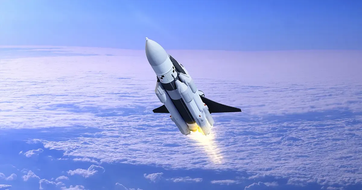
Aerospace insulation is defined by extremes. On the same platform, a designer may need to protect liquid-hydrogen fuel at −253 °C, manage avionics heat at 80 °C, and survive rocket-nozzle or re-entry temperatures above 2,000 °C. The material choice is rarely about a single property; it is the balance of thermal range, density, fire reaction, mechanical strength and lifecycle reliability. For the in-orbit and payload perspective — multilayer insulation, aerogel blankets and outgassing control — see our satellite and spacecraft thermal insulation materials guide.
This article compares the four mainstream thermal insulation families used across the aerospace and defense supply chain — rock wool, ceramic fiber, glass wool and aerogel — and maps these aerospace insulation materials to their typical military and civilian applications. The data is drawn from published thermal-property tables, industry market reports and material qualification practice.
Scope note. Aerospace insulation covers thermal, acoustic, fire and personnel-protection systems used across aircraft cabins and engine bays, launch-ground infrastructure, spacecraft thermal control and, where specified, fire-rated defense platforms. The term does not describe one product or one certification route: aerospace insulation materials range from low-temperature bagged blankets to reusable thermal protection systems, and aerospace thermal insulation is selected by service temperature, exposure duration, pressure and vibration, fire performance and maintainability — not by a single high-temperature ranking.
| Sub-system | Main boundary | Selection focus |
|---|---|---|
| On-board / cabin | Personnel areas, equipment bays, engine bays | Thermal management, smoke and toxicity, flammability, acoustics, replaceability |
| External surfaces and re-entry | Leading edges, windward and leeward surfaces, hot structures | Peak temperature, heat flux, cycles, radiation and structural coupling |
| Ground launch infrastructure | Flame diverters, flame trenches, launch pads, test stands | Short heat pulses, erosion, acoustic load, moisture and thermal shock |
| Defense and shipboard bulkheads | Fire divisions, penetrations, equipment enclosures | Fire integrity, back-face temperature rise, smoke and toxicity, mechanical load |
Because aerospace insulation spans cryogenic storage, engine bays, re-entry surfaces and ground launch structures, the sections below are organised by thermal problem rather than by material name.
1. Material Properties at a Glance
| Material | Density (kg/m³) | Thermal Conductivity (W/m·K) | Service Temperature | Fire Rating | Notes |
|---|---|---|---|---|---|
| Rock wool | 80–250 | 0.035–0.050 | −50 °C ~ +1,000 °C | A1 / non-combustible | Mature, cost-effective, needs hydrophobic treatment |
| Ceramic fiber (aluminosilicate) | 80–250 | 0.030–0.060 | −50 °C ~ +1,260 °C | A1 / non-combustible | High-temperature, soft and formable, can sinter over time |
| Glass wool | 20–100 | 0.020–0.040 | −60 °C ~ +120 °C (short-term +400 °C) | A1 / non-combustible | Light, excellent acoustic absorption |
| Aerogel / microporous | 10–100 | 0.008–0.025 | −253 °C ~ +1,200 °C (carbon-based >3,000 °C) | A1 / non-combustible | Lowest thermal conductivity, thinnest envelope |
| Calcium silicate | Project data | Project data | Typical ≤650 °C (tobermorite) to ≤1,000 °C (xonotlite) | A1 / non-combustible | Rigid, dimensionally stable fire separation; listed separately — see note below |
All four materials can achieve A1 non-combustible classification under EN 13501-1, which matters in aircraft, spacecraft and naval applications where fire load must be minimized. The real differentiator is the temperature–density–thickness trade-off.
Why calcium silicate is listed separately. Its value is rigidity, dimensional stability and non-combustible fire separation rather than a headline maximum temperature. The typical engineering range depends on phase composition — roughly 650 °C for tobermorite grades and around 1,000 °C for xonotlite grades — and those figures describe material classification, not this page's main selection table. Density and conductivity for calcium silicate must be taken from project data; they are deliberately not added to the four-family table so that table keeps a single consistent source of numbers.
2. Aerospace Applications
Aerogel: Ultra-Thin Across the Widest Range
Aerogel's combination of extremely low thermal conductivity and wide temperature range makes it the material of choice when every millimetre and every gram count.
- Cryogenic fuel systems. Liquid hydrogen at −253 °C and liquid oxygen at −183 °C both require insulation that stays effective at deep cryogenic temperatures. Aerogel blankets at 5–20 mm can replace 80–150 mm of conventional insulation, cutting boil-off and structural bulk.
- Re-entry heat shields. Silica and carbon aerogels have been used in thermal-protection systems that see thousands of degrees during atmospheric entry, sometimes as a capture medium or as a lightweight ablative/insulative layer.
- Satellite thermal control. Composite aerogel blankets in vacuum can reach effective conductivities below 0.010 W/(m·K), giving spacecraft designers tight control over equipment temperature without heavy multi-layer insulation.
- Hypersonic vehicles. At Mach 5 and above, leading-edge temperatures rise rapidly. Carbon-aerogel and ceramic-aerogel composites provide thermal protection with far less weight than traditional tile systems.
For deep-cryogenic pipework, the same design logic applies as described in our cryogenic pipe insulation guide: the vapor barrier is as important as the insulation itself.
Ceramic Fiber: The High-Temperature Workhorse
Ceramic fiber products dominate where sustained or short-duration heat exceeds 1,000 °C.
- Rocket engines. Nozzle and combustion-chamber insulation use aluminosilicate or alumina fiber felts and blankets to protect structures from hot-gas streams. A dedicated materials walkthrough of nozzles, throats and cooled hot walls is in our propulsion thermal management materials guide.
- Re-entry and reusable spacecraft. Rigid ceramic-fiber tiles and flexible blankets act as the primary thermal barrier on return vehicles. Some systems are qualified for 20+ reuse cycles with minimal mechanical degradation.
- On-board high-temperature equipment. Around auxiliary power units, thermal batteries and propulsion-system hardware, ceramic fiber keeps adjacent avionics within limits.
Rosewool supplies ceramic fiber bulk and blanket grades rated for continuous service up to 1,260 °C, suitable for engine-area insulation and high-temperature maintenance envelopes.
Glass Wool: Cabin Comfort and Cryogenic Piping
Glass wool is rarely the first choice for engine nozzles, but it plays a major role in two aerospace niches:
- Aircraft cabin acoustic and thermal lining. Modern narrow-body and wide-body programmes use ultrafine glass-wool blankets to meet strict noise-reduction targets while keeping weight low. Some new-generation glass-wool systems achieve 55 dB attenuation at below 3 kg/m².
- Cryogenic fuel lines. Hollow glass-microsphere and ultrafine glass-wool systems are used on liquid-hydrogen and liquid-oxygen transfer lines where low temperature, low conductivity and low weight are required.
Because glass wool loses strength above roughly 120 °C in continuous service, it is normally paired with other materials when both thermal and acoustic control are needed.
Rock Wool: Ground Support and Fire Safety
Direct flight hardware use of rock wool is limited by density and moisture sensitivity, but it remains important in the aerospace ecosystem:
- Ground test and launch facilities. Fire-rated partitions, engine-test-cell insulation and fuel-storage facilities use rock wool for its A1 rating and acoustic absorption.
- Non-flight structural fill. In satellites and payloads where neither extreme temperature nor minimum weight is the driver, rock wool provides low-cost fire-safe fill.
- Maintenance hangars and logistics buildings. Rock wool blanket systems protect aircraft storage and assembly areas from fire spread.
Launch Facility Fire Barriers as Civil Safety Infrastructure
A commercial or civil launch site is, first and foremost, a fire-safety problem. The same plume that threatens a flame diverter also exposes cable runs, fuel lines, payload integration halls and the personnel routes that must stay usable during a hold or abort. Insulation here is specified as civil safety infrastructure, not as a weapon system.
- Fire-rated partitions and enclosures. Rock wool, calcium silicate board and ceramic fiber systems provide the A1 non-combustible boundary around hazardous areas, equipment enclosures and escape routes. Calcium silicate earns its place where the barrier must also carry load and hold shape after heating.
- Cable and penetration protection. Fire sleeves, wraps and penetration seals based on ceramic fiber or high-silica fabric keep critical circuits alive long enough to safe the vehicle.
- Payload and integration halls. Large-volume buildings use cost-effective rock wool or glass wool systems for fire separation and acoustic control, with sealed jacketing to manage the constant condensation load.
These are the same passive-fire-protection principles used in marine and industrial A-class divisions, and they overlap with the non-combustible A1 fire-rated insulation systems we cover separately. Where a site also houses reactor or radiological research facilities, the material behaviour connects to our aerospace and nuclear insulation guide.
3. Ground and Launch Infrastructure: Flame Diverters, Test Stands and Sound Suppression
Not every aerospace thermal problem is airborne. Before a vehicle leaves the ground, its exhaust plume strikes the launch mount or a flame diverter, is turned, and is routed away through a flame trench. That short event sets a completely different design target from re-entry: the structure does not need to survive forever, it needs to be inspectable and partially replaceable within hours or days.
Flame diverter versus flame trench
The two terms are often used interchangeably and should not be. The flame diverter is the first hot-structure component that changes plume direction, taking the brunt of impingement, particle erosion and thermal shock. The flame trench is the discharge path — a lined channel that carries the turned, expanded and mixed exhaust away from the vehicle, cabling, valves and personnel routes. Published launch-infrastructure literature describes the trench as a ground-level channel bisecting the pad, with the diverter built as an inverted-V steel structure carrying a refractory lining.
That distinction matters for insulation because the two elements fail differently. A diverter panel is a localized, high-wear item designed to be swapped. A trench lining is a maintainable thermal boundary where failure usually starts at anchors, mortar joints and construction tolerances rather than in the refractory itself.
A zoned composite system, not a single refractory block
High-impingement, recirculation and particle-wear zones call for a dense refractory facing, an anchoring system, expansion and joint filler, an insulating backup layer and a structural substrate. Only in lower-erosion areas does it make sense to use ceramic fiber, rock wool or microporous layers as the primary low-conductivity element.
| Zone | Dominant load | Material logic | What the specification should say |
|---|---|---|---|
| Diverter / first impingement | High temperature, erosion, thermal shock | Dense refractory facing plus anchoring and removable liner | Panels are selected for localized erosion and thermal shock, then detailed as inspectable, replaceable modules |
| Flame trench walls and roof | Radiation, recirculation, gas erosion | Refractory masonry or castable plus insulating backup | The trench lining, not the plume path itself, is the maintainable thermal boundary |
| Launch pad and umbilical tower vicinity | Radiation, splash, acoustic load | Rigid cladding, sealing and water-tolerant systems | Launch pad insulation must remain functional after repeated wetting, heating and acoustic loading |
| Test stand thermal shielding | Steady or long-duration firing, nozzle plume | Accessible shielding with inspection clearances | A static-fire test stand trades ultimate reuse temperature for accessibility and controlled replacement |
| Water deluge zone | Water, steam, thermal cycling | Water-tolerant, drainage-compatible anchoring | Sound suppression water changes failure modes from pure heat to thermal cycling plus moisture transport |
Exposure duration changes the material route. A published subscale solid-motor hot-fire test ran for about 20 seconds, with reported nozzle insulation exposure on the order of 5,000 °C for that specific test article. Both are test-condition values, not design constants: they cannot be converted into a continuous launch pad duty, and they must not be written into the material table above. What they legitimately show is that a local hot-face environment can sit far above the continuous service range of ordinary insulation — which is exactly why the hot face and the insulation layer are specified separately.
If a firing extends from seconds into minutes, conduction depth, accumulated heat load, fastener expansion and backup temperature all increase, and the selection emphasis shifts from short-duration surface refractoriness to heat sinking, cooling and replaceable shielding.
Sound suppression is a facility protection system first
Water deluge is usually described as noise reduction, but for insulation it is a multi-physics boundary change. Water vaporizes near the plume, absorbing energy and forming a two-phase barrier, while the trench, roof or deflector geometry alters how acoustic energy propagates. Public technical references put near-field noise for large high-performance vehicles above 200 dB(A) around the base, and note that trench geometry, water injection and plume deflection all reduce the load at a given location; one documented case injected water for roughly 16 seconds before lift-off.
Neither figure should be turned into a universal design input. What they establish is the order of magnitude: sound suppression water, steam and thermal cycling arrive together, and insulation in that zone has to survive wetting, draining, re-heating and re-wetting, not just peak temperature.
Sound suppression protects the launch environment, but it also makes moisture-compatible anchoring, drainage and post-wet thermal-cycling performance part of the insulation specification.
Water deluge is not an insulation layer in its own right. It reduces the load; it does not remove it. Materials still carry residual heat after the spray stops, dry-zone heat load, and the cumulative effect of repeated cycles.
The failure chain runs backwards from the facing
Plume impingement is maintainable because the system is zoned, not because the material is indestructible. A realistic chain looks like this:
- Gas impingement and particle erosion wear the hot facing back.
- Temperature gradients and thermal cycling initiate cracking.
- Cracks accelerate erosion and let water in.
- Anchors, mortar and joints loosen under cyclic loading.
- Local spalling exposes the insulation layer and can create secondary debris.
- Capacity is restored by zoned inspection, cleaning, patching or module replacement.
Deliberate crack-instrumentation work on subscale motor testing exists precisely because heat, structure, acoustics and material defects cannot be analysed separately — one crack can change the temperature field, the flow boundary and mechanical stability at the same time.
In launch pad design, inspectability and replaceability are as important as peak-temperature resistance: refractory linings are partitioned so that impingement-zone wear can be repaired without rebuilding the entire structure.
Test stands are not launch pads
A test stand is a controlled facility: instrumentation can be placed close to the article, drainage and access are designed in, and spare modules are held on site. That makes removable panels, water-cooled elements or active thermal management realistic. A launch pad operates under lift-off windows, recirculation risk, vehicle interfaces and turnaround pressure, so it favours zoned refractory facings and a fast inspection routine instead.
Both share the same hot-face logic, and neither can be specified from a single peak temperature.
Spacecraft and Satellite Thermal Control
Beyond launch and re-entry, the largest day-to-day insulation problem in space is steady-state thermal control: keeping electronics, batteries, optics and cryogenic payloads inside their allowable temperature bands while the vehicle moves between sun and shadow. In orbit there is no air, so convection disappears and radiation dominates — which changes the material logic completely.
- Passive control comes first. Multi-layer insulation (MLI) — alternating low-emissivity films and thin spacers — is the baseline for almost every satellite and spacecraft bus. Radiators, louvers, optical solar reflectors and selective coatings then trim the balance. The spacers must not compact under launch vibration or creep over a multi-year mission, so low-outgassing inorganic materials are preferred.
- Active control backs it up. Electric heaters, fluid loops and heat pipes move heat from warm avionics to radiating surfaces when passive design alone is not enough.
- Cryogenic payloads. Instruments and sensors that need deep cold — infrared detectors, superconducting elements, propellant management — rely on aerogel and microporous layers combined with MLI. The same non-combustible, low-outgassing character that makes aerogel attractive for vacuum service also keeps total mass low, which is why it appears on both cryogenic lines and instrument enclosures. For the sensor-package side of that picture — probe-to-electronics gradients and dielectric interlayers — see our high-temperature insulation guide for aerospace sensors.
The outgassing limits discussed in Section 6 — total mass loss and collected volatile condensable materials — are what make spacecraft insulation a separate discipline from ground or launch-pad work. For the radiation-hardening and nuclear-facility side of the same material behaviour, see our guide to aerospace and nuclear insulation; for cryogenic line design the same logic applies as in our cryogenic pipe insulation guide.
4. Aircraft Insulation Systems: Cabin, Cargo Bay and Engine Bay
A transport aircraft carries insulation in three very different environments, and each one is specified on its own logic. Understanding the split is usually more useful than comparing material data sheets.
Cabin: thermal-acoustic blankets with a fire-blocking layer
The visible interior lining is only the cosmetic layer. Behind it sits a thermal-acoustic insulation blanket — usually an ultrafine glass-fibre batt at 6–16 kg/m³, encapsulated in a polymer film bag. It does three jobs at once: hold cabin temperature, cut airframe noise, and slow a fire long enough for passengers to get out.
That last job is why transport-category rules require insulation inside the pressure vessel to pass a burnthrough-resistance test on top of the normal flammability checks. Modern blankets meet it with a fire-blocking layer: a thin high-silica or ceramic-fibre fabric, typically 0.3–2 mm thick and 100–300 g/m², placed on the outboard face of the bag. It contributes almost nothing to thermal performance. Its value is time — it resists flame penetration and holds the blanket together so a cabin fire does not reach the fuselage skin quickly.
For the textile part of that assembly, ceramic fiber cloth in woven or needled form is the usual starting point, chosen for temperature capability and for how it behaves under flame rather than for conductivity.
Cargo bay: fire containment and moisture management
Cargo compartments are designed around containment, so the insulation there is paired with a liner that must hold a fire until the suppression system discharges. Two practical requirements dominate: the insulation must not hold water (condensation on the inside of the fuselage skin is constant in service), and it must be removable for inspection. Bagged blankets with sealed seams and deliberate drainage paths are the standard answer, and any absorbed moisture is treated as a weight and corrosion problem, not just a thermal one.
Engine bay and APU zone: continuous high temperature
Behind the firewall the criteria change completely. Insulation here sees 500–1,000 °C, continuous engine vibration, and fuel and hydraulic fluid contamination. Aluminosilicate ceramic fiber blanket and formed rigid parts are used, normally foil- or cloth-faced and clamped rather than bonded. Maintenance access drives the mechanical design: blanket sections have to be removed and refitted many times without losing thickness or compressing permanently.
| Zone | Temperature range | Typical insulation form | Governing requirement |
|---|---|---|---|
| Cabin | −55 °C to +85 °C | Bagged ultrafine glass wool, 6–16 kg/m³ | Burnthrough resistance, smoke and toxicity, areal weight |
| Cargo bay | Ambient to +200 °C | Bagged blanket, sealed seams, drainage | Fire containment, moisture management, inspectability |
| Engine bay / APU | 500–1,000 °C | Ceramic fiber blanket, formed parts, foil facing | Temperature, vibration, fluid resistance, removability |
5. Reusable Launch Vehicles and Re-entry Thermal Protection
Reusability is often presented as a material substitution — a better tile replaces an ablative shield. In practice a thermal protection system is a zoned assembly, and reuse is an operating model, not a material property.
Zoning is the selection logic
Publicly documented reusable orbiter programmes divided the vehicle surface by temperature and structural function, and that zoning remains the clearest way to explain the choice:
| Zone | Typical system | Temperature boundary (historical vehicle) | Engineering meaning |
|---|---|---|---|
| Nose cap and wing leading edges | Reinforced carbon-carbon and hot structure | Highest temperature region | Shape retention, oxidation resistance, thermal cycling |
| Windward lower surface | High-temperature reusable surface insulation | About 650–1,260 °C | High radiative emission, insulation, thermal-shock resistance |
| Leeward and upper surfaces | Low-temperature reusable surface insulation | Below about 649 °C | Light weight, conformability, maintainability |
| Lower-temperature areas | Flexible reusable surface insulation | Below about 370 °C | Blanket coverage and joint control |
Those boundaries describe one extensively documented winged reusable vehicle. They are useful as a working example of zoned re-entry design, not as a universal material boundary for every reusable rocket now flying.
What rigid tiles actually trade
In a reusable thermal protection system, rigid tiles achieve low conductivity through a porous ceramic body — historical figures put low-density tiles near 144 kg/m³ and higher-density tiles near 352 kg/m³, with thickness from roughly 12.7 mm to 127 mm depending on local heat load. Those are typical values for that vehicle, and they should not be back-filled into the four-family table in Section 1, which describes broad engineering ranges rather than one qualified product.
Rigid tiles provide low conductivity through a porous ceramic body, but their reusable performance depends on coatings, strain isolation, attachment and damage inspection — not density alone.
The costs are brittleness, attachment tolerance and joint maintenance. Tile fragility, water absorption and gap upkeep on the historical vehicle are the standard cautionary example: reusable never meant maintenance-free.
Ablative versus reusable
For a reusable rocket, the two routes solve different problems:
- Ablative insulation consumes mass — decomposition, charring, melting or sublimation carry heat away. It suits a short, extreme heat pulse, a single mission, or a very high heat load where material consumption is acceptable.
- Reusable systems retain the body and rely on low conductivity, radiative emission, hot structure and mechanical attachment, accepting inspection, repair and recertification after every flight.
Ablative insulation is selected when a short, extreme heat pulse can be accepted as material consumption; reusable TPS is selected when inspection, repair and recertification are part of the operating model.
Five boundary judgments follow from that: ablative keeps clear value for single, extreme, short-duration missions; multi-mission designs must weigh inspection, repair, certification and turnaround time together; the hottest local points may be hot structure rather than insulation; flexible insulation suits lower-temperature, conformable, large-area regions; and cycle life is only defined by heat flux, dwell time, peak temperature and the inspection regime together — never by a material name.
Where the four families interface with TPS
| Family | Where it fits | Where it should not be assumed |
|---|---|---|
| Ceramic fiber | Mid-to-high temperature insulation, flexible blankets, composite layers | Leading edges and long-duration erosion surfaces |
| Aerogel / microporous | Low-to-mid temperature, space-constrained insulation | Carrying re-entry erosion on its own |
| Rock wool | Ground facilities, equipment bays, background bulkhead insulation | Certified cabin interiors or re-entry surfaces without project evidence |
| Glass wool | Low-temperature equipment insulation | Anything above its continuous service range |
These are engineering interfaces, not equivalences. Reaching a temperature in the table does not qualify a material as flight TPS; thermal structure, attachment, environment, smoke and toxicity, and cycle verification still apply.
For a reusable rocket, the practical conclusion is that a thermal protection system is specified as a maintained asset: flown, inspected, repaired where allowed, and recertified. No material should be described as infinitely reusable.
Reusable Booster Insulation and Flight Turnaround
The commercial drive to recover and refly boosters has made turnaround a primary design variable. A thermal protection system on a reused booster is not a one-shot consumable; it is a maintained asset that must be inspected, repaired where allowed, and recertified before every flight.
- Flexible blankets on the booster body. Large surface areas away from the highest heat flux are typically covered with flexible ceramic fiber blankets — the same aluminosilicate families used in aircraft engine bays — faced, clamped and zoned for removal. They can be a ceramic fiber blanket grade rated for continuous service up to about 1,260 °C, qualified for vibration and repeated removal.
- Ablative on the engine section. The engine and nozzle region sees the most extreme, short-duration pulse, so ablative or dense refractory materials are still preferred there even on a reusable vehicle — reuse applies to the structure, not necessarily to the hottest local material.
- The inspection regime is the product. What makes a booster reusable is the documented workflow: post-flight inspection for thinning, cracking and fastener loss; zoned patch or module replacement; and recertification against the original thermal and structural limits. No material is "infinitely reusable"; the operating model is.
This civil, commercial framing — recover, inspect, refly — is where most new aerospace insulation demand now comes from, well beyond any single defence programme.
6. Aerospace vs Industrial Insulation: Five Differences That Change the Spec
Engineers who move from a power plant or a petrochemical project into an aerospace programme usually find the thermal calculation is the easy part. Five other things decide the specification.
- Weight is a design variable, not a cost variable. On a building, choosing 40 kg/m³ over 100 kg/m³ is mostly a price and handling decision. On an aircraft, every kilogram of insulation is payload or fuel that cannot be sold, so the spec is written in areal weight (kg/m² or g/m²), and the material is normally picked at the lowest density that still survives handling and vibration.
- Outgassing matters as soon as there is a vacuum. Materials for spacecraft and high-altitude bays are screened for volatile content. The common screening method reports total mass loss (TML) and collected volatile condensable materials (CVCM), with acceptance limits in the order of 1.0 % TML and 0.10 % CVCM. Condensables are the real enemy: they redeposit on optics, sensors and thermal-control surfaces.
- Fire performance is measured in minutes, not in classifications. A1 / non-combustible is the entry ticket, not the requirement. Aircraft rules add burnthrough resistance, heat release, smoke density and toxicity. An industrial ceramic fibre blanket with an excellent A1 rating can still fail an aviation fire spec because of its binder content or its smoke behaviour.
- Vibration, thermal cycling and shedding. Airborne equipment is qualified against environmental standards that combine temperature and altitude cycling, vibration, humidity and salt fog in one sequence, and that series is the reference point across the industry. Insulation that is perfectly happy on a static duct can shed fibres, dust or binder after a few thousand hours of vibration — and loose conductive fibres in an avionics bay is a reliability problem, not a housekeeping one.
- Traceability outruns performance. Aerospace programmes require batch-level certification, retained samples and a qualification tied to a specific manufacturing route. Changing a binder supplier can trigger requalification. In practice the buyer's question is rarely "which material performs best" but "which material can be supplied unchanged, with paperwork, for the next ten years".
Our aerospace and defense application page shows where these materials land in a complete assembly.
7. Fire Barriers, Burnthrough Resistance and Fire-Blocking Layers
Fire performance on an aircraft or a defense platform is a property of the complete assembly under a defined exposure, not of an insulation blanket's room-temperature conductivity. A fire barrier is therefore specified as an assembly, not as a blanket.
Two different failure objects
A cargo-compartment fire barrier and a cabin fire-blocking layer are trying to prevent different things:
- The cargo boundary must delay flame, heat and smoke passing from the cargo volume into the cabin. Liners, floor panels and bulkheads form the barrier, and penetrations, joints, cable runs and duct openings are the weak paths.
- Cabin materials — seat cushions, wall panels, textiles — need a fire-blocking layer or equivalent behaviour so that they do not contribute rapid flame spread, heat release or toxic smoke.
Aviation material requirements cover vertical and horizontal burn behaviour, cargo-liner burnthrough and separate heat-release and smoke-density evaluation. The exact limits belong to the applicable aviation requirements and the approved assembly, not to a generic insulation data sheet.
Burnthrough resistance describes how long a barrier resists through-penetration under a defined fire exposure, including edge sealing and substrate interaction; it is not an arbitrary maximum service temperature.
Fire seals are tested with their neighbours
A fire seal closes the path for heat, flame and smoke. Its durability depends on the material plus compression, joint geometry and substrate, which is why seal performance cannot be read off a fibre specification. Common engineering approaches include intumescent or ceramic fiber packing, high-temperature fabrics or blankets, sealants and coatings, and metal or composite protection layers. Aviation service adds compression set, vibration, fluid exposure, ageing and repeated removal.
Fire seals perform as part of a joint: material alone cannot establish burnthrough resistance without substrate, compression and test conditions.
Where calcium silicate fits
Calcium silicate earns its place through rigidity and fire integrity rather than a headline temperature. It is a non-combustible, low-conductivity, dimensionally stable board that can carry load, accept fixings and hold shape after heating — which is why it is used for bulkheads, deck linings, fire-door cores, equipment enclosures and pipe or penetration divisions.
Two cautions keep the specification honest:
- Typical range is set by phase composition. Tobermorite grades are commonly quoted around 650 °C and xonotlite grades around 1,000 °C. These describe material classification and are deliberately kept out of the Section 1 table, so the page does not end up with two competing sets of numbers. Density and conductivity must come from project data.
- Fire division is a system rating. Marine and platform practice evaluates a division such as an A-60 boundary for integrity and back-face temperature rise over a defined period. Calcium silicate board may form part of such a system where strength and insulation are both required — but that is a statement about the tested assembly, not about the board on its own.
Calcium silicate is suited to fire-rated partitions and equipment enclosures where board strength, dimensional stability and post-fire integrity matter; the exact service temperature depends on composition, density and the approved system.
Finally, a calcium silicate fire barrier should not be confused with ablative TPS. Re-entry protection works through external radiation, ablation or hot structure plus post-flight inspection; calcium silicate belongs to fixed passive fire protection. Both are thermal protection, but the load duration, structural function and acceptance route are different.
8. Harsh Environments: Vacuum, Vibration, Salt Fog and Radiation
Beyond the airframe, aerospace thermal insulation is asked to survive conditions that never appear in a building services specification.
- Vacuum and thermal cycling in orbit. With no air, convection disappears and radiation dominates. Multi-layer insulation — alternating low-emissivity films and thin spacers — is the standard answer, and the spacers must not compact under launch vibration or creep over a 15-year mission. Low Earth orbit adds atomic oxygen and ultraviolet exposure, both of which attack polymer films and organic binders first.
- Salt fog and humidity on naval and coastal platforms. Shipboard installations are specified for long salt-spray exposure. Insulation with high water absorption loses thermal performance and, worse, drives corrosion under insulation on the pipe or bulkhead beneath it. Low-chloride hydrophobic grades and correctly sealed jacketing matter more here than the nominal conductivity figure.
- Ionizing radiation. Spacecraft, high-altitude platforms and nuclear-facility installations all see ionizing radiation, which degrades organic binders and polymer facings long before it affects the inorganic fibre itself. The usual mitigation is to specify inorganic or very low-binder grades and to keep the organic content of the whole assembly — films, adhesives, sewing thread — as low as the design allows.
- Ground support is not exempt. Test cells, launch structures and maintenance hangars carry the same fire and acoustic loads as the vehicle itself, which is where conventional rock wool blanket and board systems earn their place in the programme.
For the nuclear side of this topic — reactor buildings, containment and radiation shielding — see our dedicated guide to aerospace and nuclear insulation. This section deliberately stops at the material-behaviour boundary so the two articles do not overlap.
9. Defense Applications
Defense platforms push insulation in different directions: soldier survivability, missile speed, ship survivability and electromagnetic stealth.
Aerogel in Defense
- Personal protection. Thin aerogel layers integrated into cold-weather gear and vehicle interiors provide thermal protection without the bulk of legacy insulating materials.
- Radiation shielding. The nanoporous structure can adsorb radioactive particulates, useful in nuclear facilities and certain naval systems.
- Fire barriers. Composite aerogel blankets meet A1 non-combustible requirements while adding minimal weight to vehicle and ship compartments.
Boron Nitride Fiber: High Heat Plus Electromagnetic Transparency
Boron nitride fiber is not a mainstream commodity, but it is critical in specialized defense systems:
- Missile radomes. Its low dielectric constant and loss tangent allow radar signals to pass through while the material survives the aerodynamic heating of high-speed flight.
- Rocket nozzles. Woven boron nitride textiles tolerate gas temperatures above 2,800 °C in inert atmospheres.
- Stealth and infrared suppression. Low thermal conductivity reduces infrared signature, while carbon-aerogel and BN composites can be tuned for radar absorption.
Ceramic Fiber in Defense
- Missile motor insulation. Ceramic fiber blankets and felts protect motor cases and nozzle structures from combustion temperatures.
- Hypersonic thermal barriers. Reusable ceramic-fiber composites are being qualified for leading edges and nose cones on maneuvering hypersonic vehicles.
- Ship and submarine systems. High-temperature exhaust and auxiliary-system insulation on naval vessels often use ceramic fiber for its corrosion and heat resistance.
Glass Wool in Defense
- Naval ships. Engine-room piping, bulkhead insulation and cabin partitioning on military vessels use glass wool for fire safety, acoustic control and thermal management. Systems are typically specified with high density, low water absorption and long salt-spray resistance.
- Ground vehicles and shelters. Glass wool provides a cost-effective, non-combustible thermal and acoustic liner for command posts and transport shelters.
10. Market Trends and Supply-Chain Considerations
The global aerospace insulation market is estimated at roughly USD 1.0–1.6 billion in 2025, with projected compound annual growth of 5–8.7 % through the early 2030s. Key drivers include:
- Commercial aviation recovery and fleet renewal programmes.
- Reusable rockets and reusable launch vehicles, which multiply the demand for durable thermal-protection materials.
- Hypersonic programmes, both civil research and defense, pushing materials above 1,500 °C.
- Green-aviation targets, encouraging lighter insulation that improves payload and fuel efficiency.
Aerogel and ceramic-matrix composites are expected to grow faster than the overall market, increasing their combined share from roughly 12 % to more than 25 % by 2032.
Supply-Chain Notes
Recent tariff actions have affected several raw-material categories, including certain fiberglass fabrics and high-silica textiles. For export-oriented projects, engineers and buyers should:
- Qualify second-source suppliers early.
- Consider regional production or bonded warehousing for sensitive programmes.
- Document material traceability and certification from the start.
11. How to Select an Aerospace or Defense Insulation Material
Aerospace thermal insulation is selected in the same order as any other engineering material: use temperature as the first filter, then refine by weight, space and functional requirements. The difference is that aerospace insulation materials are also filtered by exposure duration, certification route and how often the part has to come off for inspection.
| Temperature Regime | Preferred Material | Typical Use |
|---|---|---|
| > 1,200 °C sustained | Alumina / SiC ceramic fiber, boron nitride | Rocket nozzles, leading edges, re-entry tiles |
| 500 °C – 1,200 °C | Ceramic fiber, aerogel composite | Engine compartments, APU zones, exhaust systems |
| −150 °C – 120 °C | Glass wool, aerogel | Cabin liners, cryogenic lines, fuel systems |
| < −150 °C | Aerogel / microporous, hollow-glass microspheres | Liquid-hydrogen storage, deep-space probes |
| Multifunction (thermal + acoustic + fire) | Engineered composites / layered systems | Aircraft cabin, naval ships, crew compartments |
When the application requires more than one function — for example thermal control plus radar transparency plus ablation resistance — the answer is almost always a composite rather than a single material. The same logic applies to fire: where a fire barrier is required, the qualified object is the assembly — facing, insulation, sealing and substrate — not a single blanket.
12. Future Trends
Four trends are reshaping aerospace and defense insulation:
- Lower conductivity at lower weight. Silica aerogels are targeting conductivities below 0.005 W/(m·K), while new ceramic-fiber felts maintain strength above 1,500 °C.
- Scalable manufacturing. Ambient-pressure drying for aerogel and green chemistry for boron nitride fiber are expected to reduce cost and environmental impact.
- Reusable systems. Reusable rocket programmes are asking for thermal-protection materials that survive 20+ flight cycles with predictable degradation.
- Digital qualification. AI-assisted modelling of material microstructure is shortening the time from lab sample to flight qualification.
13. Conclusion
Aerospace insulation is not a one-material market. Rock wool, ceramic fiber, glass wool and aerogel each occupy a distinct zone in the temperature–weight–cost map. The right specification usually combines materials: aerogel for the thinnest cryogenic envelope, ceramic fiber for engine and re-entry heat, glass wool for cabin acoustic and thermal comfort, and rock wool for ground-support fire safety.
Rosewool manufactures ISO 9001-, CE- and SGS-certified insulation materials spanning rock wool, ceramic fiber, glass wool and nano/microporous insulation, with a supply base established in 1982. For project-specific material selection, thermal calculations or certification support, contact our technical team with your operating temperature, weight target and applicable standard.
For related reading, see our guides on non-combustible A1 fire-rated insulation systems and aerogel versus traditional insulation.
Explore flexible aerogel and microporous insulation options in our aerogel insulation guide.
Frequently asked
What insulation is used for rocket engines? +
Rocket engines typically use ceramic fiber blankets or felts for nozzle and combustion-chamber insulation because they withstand sustained temperatures above 1,000 °C. For cryogenic fuel tanks, aerogel and microporous insulation are preferred for their extremely low conductivity at −253 °C.
Why is aerogel used in spacecraft? +
Aerogel offers the lowest thermal conductivity of any solid insulation and remains effective across a very wide temperature range, from deep cryogenic to over 1,200 °C. This lets spacecraft designers save weight and volume on thermal protection and fuel-system insulation.
What is the best insulation for cryogenic fuel tanks? +
Aerogel blankets and microporous insulation are the leading choices for liquid-hydrogen and liquid-oxygen systems because a 5–20 mm layer can replace 80–150 mm of conventional insulation. Hollow-glass-microsphere systems are also used on some transfer lines.
How do thermal protection tiles work on re-entry vehicles? +
Re-entry tiles are made from rigid ceramic-fiber or silica-fiber composites with very low thermal conductivity. They absorb and radiate away frictional heat while keeping the vehicle structure within safe temperatures. Reusable systems are qualified for multiple flights.
What certifications matter for aerospace insulation? +
Key certifications include EN 13501-1 fire reaction (A1 non-combustible preferred), applicable aviation flammability requirements where required, ISO 9001 quality systems, and project-specific material traceability. Military programmes may add defense-standard qualification and salt-spray testing.
What insulation materials are used in aircraft cabins? +
Cabin insulation is a bagged thermal-acoustic blanket, usually ultrafine glass fibre at 6–16 kg/m³ sealed inside a polymer film, with a fire-blocking fabric layer on the outboard face. It has to deliver thermal control, noise reduction and burnthrough resistance at the same time. Where temperatures rise above what glass wool can handle — engine bays and APU zones — ceramic fiber replaces it.
What is a fire-blocking layer in aircraft insulation? +
A fire-blocking layer is a thin high-silica or ceramic-fibre fabric, typically 0.3–2 mm thick and 100–300 g/m², fitted to the outside of the insulation bag. It adds almost no thermal value on its own. Its job is to resist flame penetration and hold the blanket together, so a cabin fire takes much longer to reach the fuselage skin and the structure keeps its integrity.
How is aerospace insulation different from industrial insulation? +
Five things change the specification: weight is written as areal mass rather than bulk density; outgassing is screened for vacuum service; fire acceptance includes burnthrough resistance, smoke density and toxicity rather than non-combustibility alone; the material must survive vibration and thermal cycling without shedding fibres; and batch-level traceability is mandatory for the life of the programme.
Which insulation is used in aircraft engine bays? +
Aluminosilicate ceramic fiber blanket and formed rigid parts rated for continuous service up to 1,260 °C, normally foil- or cloth-faced and held with clamps rather than adhesive. The design is driven less by conductivity than by temperature, vibration, resistance to fuel and hydraulic fluid, and the need to remove and refit sections during maintenance without losing thickness.
Do aircraft insulation materials need to be tested for outgassing? +
Yes, for any vacuum or high-altitude application. Materials are screened for total mass loss (TML) and collected volatile condensable materials (CVCM), with acceptance limits commonly around 1.0 % TML and 0.10 % CVCM. The reason is not the material itself but what it releases: condensables redeposit on optics, sensors and thermal-control surfaces and degrade them over time.
What does "aerospace insulation" cover? +
Aerospace insulation covers thermal, acoustic, fire and personnel-protection systems across four sub-systems: on-board cabins and equipment bays, external surfaces and re-entry thermal protection, ground launch infrastructure such as flame diverters and test stands, and fire-rated defense or shipboard bulkheads. The term does not imply a single certification route — each sub-system is qualified against its own requirements.
How is a flame diverter different from a flame trench? +
A flame diverter is the first hot-structure component that changes plume direction, taking impingement, particle erosion and thermal shock directly. A flame trench is the discharge path — a lined channel that carries the turned and expanded exhaust away from the vehicle. Diverter panels are designed as localized, replaceable wear items, while the trench lining is a maintainable thermal boundary where failure usually starts at anchors and joints.
Why does sound suppression change insulation requirements? +
Water deluge changes more than noise. It alters temperature, pressure, acoustic and moisture boundaries at once: water vaporizes near the plume, forms a two-phase barrier, and then leaves the insulation wet. Materials in that zone must survive thermal shock, repeated wetting and drying, drainage provision and moisture-compatible anchoring — not just peak temperature.
Can reusable rockets reuse the same insulation indefinitely? +
No. Reusability is an operating model, not a material property. A reusable thermal protection system is flown, inspected, repaired where the programme allows, and recertified. Cycle life is defined by heat flux, dwell time, peak temperature and the inspection regime together, so no insulation should be described as infinitely reusable.
When is ablative insulation preferred over reusable TPS? +
Ablative insulation is preferred when a short, extreme heat pulse can be accepted as material consumption — a single mission, a very high heat load, or a case where carrying inspection and repair capability costs more than the material. Reusable thermal protection is preferred when inspection, repair and recertification are already part of the operating model.
Does calcium silicate replace ceramic fiber? +
Not on a temperature ranking. Calcium silicate provides rigidity, dimensional stability and non-combustible fire separation for bulkheads, deck linings, fire-door cores and equipment enclosures, while ceramic fiber serves mid-to-high temperature insulation and flexible blankets. Their typical ranges come from different tests, so any substitution has to be justified by the complete assembly rather than a maximum-temperature figure.
How is satellite thermal control different from launch-pad insulation? +
On the pad the problem is short, extreme heat pulses, erosion and acoustic load from the plume. In orbit it is steady-state radiation balance with no convection, solved by multi-layer insulation, radiators and low-outgassing materials. The material priorities — vacuum stability and minimal outgassing — are almost opposite to those of a flame diverter.
Can a reusable rocket use the same insulation every flight? +
Not without inspection. Reusable boosters treat the thermal protection system as a maintained asset: post-flight inspection for thinning and cracking, zoned repair or module replacement, and recertification against the original limits. Ablative sections on the engines are still consumed; flexible ceramic-fiber blankets on the body are inspected and reflown.
Request a quote
Interested in our insulation solutions? Send us your requirements and our team responds within one business day.