
Rock Wool External Wall Insulation: European ETICS Techniques
ETICS rock wool external wall insulation guide: U-value and thickness, anchor wind-load calculation, horizontal fire barriers, condensation control and service life.
Why European ETICS Practice Matters for Rock Wool Facades
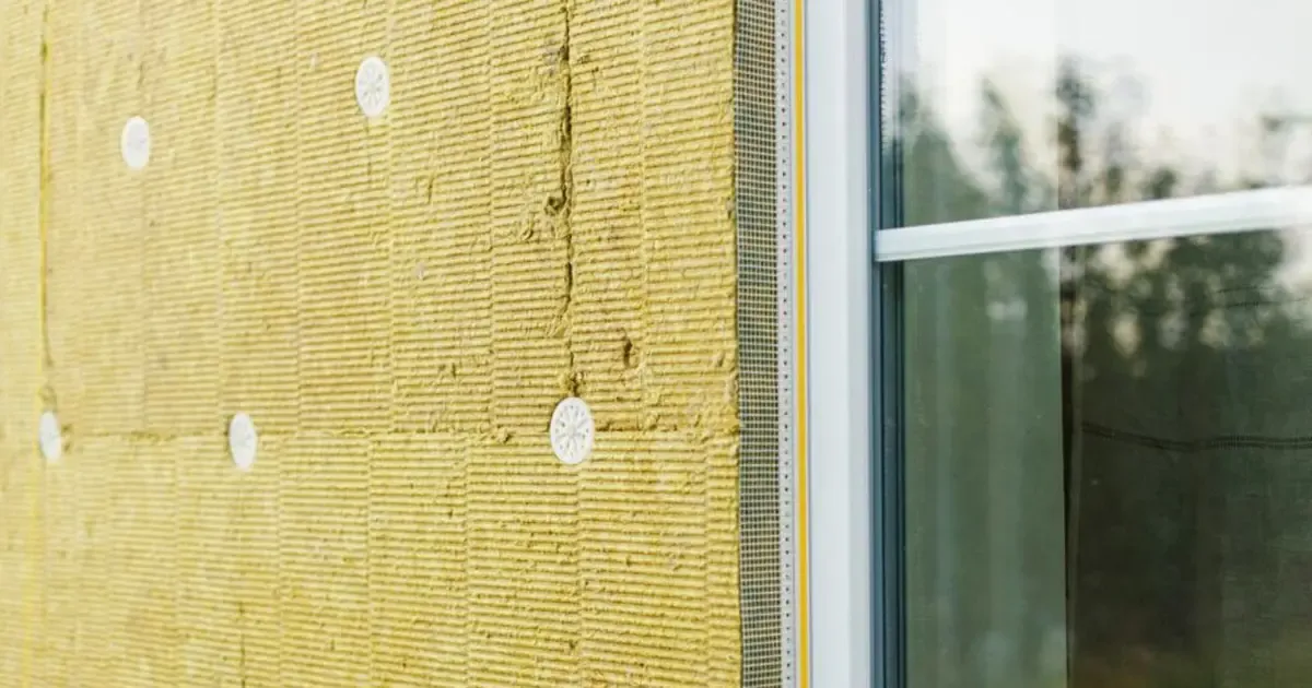
Rock wool is an A-class (non-combustible) high-performance insulation with a long, well-documented history in European External Thermal Insulation Composite Systems (ETICS). The maturity of its installation standards and quality-control discipline far exceeds what is common elsewhere. This article distils European practice — built on ETAG 004, EN 13500 and EN 17237 — into a practical reference for external wall insulation, covering how thick the board has to be, how many anchors a given wind zone actually needs, how horizontal fire barriers stop vertical flame spread, and what governs moisture behaviour over a 25-year service life, so that facade projects anywhere can adopt internationally proven methods. For the full material family behind this guide, see the rock wool insulation hub.
The single most useful idea in external wall insulation is that the board is the least interesting part of the system. Bonded area, anchor pattern, fire-barrier continuity and the vapour path through the build-up decide whether a facade performs for twenty-five years or starts cracking and staining in five. Every number in this guide is a system number, and that is how a rock wool external wall should be specified.
1. System Build-Up and the Standards Framework
European rock wool facade systems follow two pillars: the European Technical Assessment (ETA) route and the harmonised EN route. ETAG 004 is the certification core for rendered ETICS, while EN 13500 specifies performance requirements for mineral-wool-based systems. In 2022, EN 17237 (ETICS kits with rendered systems) was published, replacing EAD 040083-00-0404 and giving manufacturers more flexibility to tune components such as anchor spacing and render thickness within a defined field of application.
Three basic build-ups dominate:
- Double-mesh with disc-anchored mesh — substrate → levelling → adhesive → rock wool board → two glass-fibre mesh layers (one below, one above the anchor disc) → base coat → finish. Best for tall buildings needing high flatness and crack resistance.
- Single-mesh with disc-anchored mesh — same sequence with one mesh layer. Lower cost, suited to less demanding flatness requirements.
- Strip-anchored single mesh — uses rock wool lamellas (fibres perpendicular to the wall) with higher tensile strength, ideal for weak substrates.
Disc diameter is the key differentiator: ≥ 60 mm in double-mesh systems, ≥ 140 mm in single-mesh systems, and ≥ 60 mm in strip-anchored systems. This sizing reflects how the anchoring system affects overall thermal and mechanical performance.
2. Thickness, U-Value and Thermal Bridging
"How thick should external wall insulation be?" is the question specifiers ask first, and it is the one question a board datasheet cannot answer. Thickness is an output of a calculation that starts with the wall you already have, not with the insulation you would like to sell.
The arithmetic runs in one direction. Convert the target U-value to a total thermal resistance: R = 1 / U. Subtract the resistances the assembly already provides — inner surface film (0.13 m²·K/W for horizontal heat flow), outer surface film (0.04 m²·K/W), and the existing masonry and plaster layers taken as thickness divided by design conductivity. What is left is the resistance the insulation alone must deliver, and thickness = R × λ. Use the declared thermal resistance from the Declaration of Performance rather than thickness divided by a rounded lambda: the declared figure is the one a building-control officer can trace to a U-value. The summing method itself is set out in EN ISO 6946. Design conductivity for rock wool external wall boards typically falls between 0.034 and 0.040 W/(m·K), and the value on the Declaration of Performance governs.
Worked once, the numbers stop being abstract. For a target U-value of 0.30 W/(m²·K) on a 215 mm brick wall, the total resistance required is 3.33 m²·K/W; after the surface films and the masonry are removed, roughly 2.98 m²·K/W has to come from the board. At a rock wool design conductivity of 0.035 W/(m·K) that is about 104 mm. Published system calculations land in the same place: mineral wool at 0.036 W/(m·K) reaches 0.30 W/(m²·K) at 110 mm on 215 mm brickwork and 120 mm on 200 mm dense blockwork, while a graphite EPS board at 0.032 W/(m·K) does it at 90 mm and 100 mm respectively. Rock wool needs perhaps 20–30 mm more than EPS for the same U-value, and that is the entire thickness penalty — a detail, not a disqualifier. Glass wool sits in the same band and is chosen on the same arithmetic, with fire class and service temperature as the tiebreakers.
Most conventional retrofit work settles between 90 and 120 mm. Deep retrofit and low-energy work runs 150–200 mm. The reason thickness dominates the result is simple arithmetic: moving from 100 mm to 200 mm adds about 3.15 m²·K/W to the assembly, which is more resistance than most solid masonry walls contribute in total. Insulation is the only lever in the build-up with that much range.
Then the anchors claw some of it back. Every fixing that penetrates the insulation is a small thermal bridge, and the correction is explicit: Uc = U + χp × n, where n is the number of anchors per square metre and χp is the point thermal transmittance of one fixing. Where the anchor's own technical approval does not state a value, 0.004 W/K is taken for a galvanised steel screw with a plastic-covered head and 0.002 W/K for a stainless screw with a plastic cover or an air gap at the head. The correction only has to be carried when χp × n exceeds 0.04 W/(m²·K) — below that it is lost in rounding.
Two consequences follow from that. The first is thermal: specifying stainless fixings, or fixings with an insulated cap, halves the point loss at no cost to holding power. The second is visual, and it is the one that generates complaints. Fastener points run marginally colder than the surrounding render, so they attract moisture and airborne dust and print themselves on the facade as a faint regular grid — the "leopard" or tile-ghosting pattern. The fix is the same in both cases: recessed anchors with an insulating cap, and no more anchors than the wind calculation actually requires. Every extra fixing is another thermal bridge, which is the whole argument for calculating the number instead of guessing it.
Linear thermal bridges matter more than the point ones. A balcony slab punching through the insulation layer, a window reveal left uninsulated, or a base detail where the insulation layer is interrupted will each drop the local internal surface temperature below the dew point of the room air, and that is where condensation forms and mould appears. External wall insulation is uniquely good at suppressing these because it wraps the structure instead of sitting inside it — but only if the wrap is continuous. A thermal bridge that survives a retrofit is almost always geometric — a slab, a reveal or a base detail — not a material one.
3. Board Bonding and Anchoring
Substrate preparation and primer
European standards are strict: substrate flatness deviation ≤ 3 mm/m, verticality ≤ 2 mm/2 m — tighter than the ≤ 5 mm/m commonly required elsewhere. The sequence: high-pressure washing (≥ 6 MPa) to remove dust and oil; a silane-coupling / nano-silica primer forming Si–O–Si covalent bonds; and cementitious levelling (≤ 15 mm per layer, ≥ 24 h between coats). Primer thickness is 0.8–1.2 mm, applied at ≥ 5 °C and ≤ 85% RH; cold-climate epoxy-modified primers allow work down to −35 °C.
Bonding sequence: anchor-first, then bond
European practice reverses the usual order — anchor first, then bond. Steps: pre-drill with hole depth 10 mm beyond the effective anchor depth; select anchors by substrate (concrete pull-out ≥ 0.6 MPa, masonry ≥ 0.3 MPa); drive discs flush or 1–2 mm recessed to avoid finish cracking; apply adhesive by the strip-and-dab method (50–80 mm perimeter bead plus 8–10 dabs ≈ 100 mm); require tensile bond ≥ 0.60 MPa (wet) and ≥ 0.40 MPa (water-aged).
Effective bonded area must be ≥ 50%. Anchor count is calculated from building height and wind load: 6–8 /m² generally, densified to 8–10 /m² at the ground floor, corners and openings. Embedment: ≥ 30 mm in concrete, ≥ 50 mm in masonry.
Base coat and mesh embedding
Base coat thickness is typically 5–7 mm (tolerance ≤ 3 mm/m). Apply 3–5 mm first, embedding alkali-resistant glass-fibre mesh (≥ 160 g/m²) while wet with ≥ 100 mm overlaps; once initial set, apply a second 2–3 mm pass. European standards specify 45° diagonal mesh overlaps to improve crack resistance — and never allow dry-laid mesh, which creates stress concentrations.
4. Critical Detailing at Special Locations
Opening fire-stop borders
ETAG 004 requires a fire-stop border ≥ 100 mm wide around every door and window. Method: pre-embed A-class rock wool strips of the same thickness; fit ≥ 100 mm stainless or galvanised metal edge profiles (≥ 0.8 mm, anchored ≤ 300 mm); seal with weather-resistant silicone (≥ 50% movement, 12–15 mm wide, ≥ 5 mm deep, passing EN 1609); and add 300×400 mm diagonal mesh reinforcements at corners. Anchors around openings are densified to ≤ 300 mm spacing with at least 3 per side.
Internal/external corners with metal beads
European standards mandate rigid metal corner beads — not the mesh-only reinforcement common elsewhere. Beads are hot-dip galvanised steel (≥ 1.2 mm), aluminium (6063-T5, ≥ 10 µm oxide) or stainless (304, ≥ 0.8 mm), fixed before the base coat (vertical ≤ 400 mm, horizontal ≤ 600 mm). At external corners, double mesh (≥ 400 mm total) wraps the bead.
Movement and expansion joints
A three-layer system is standard: breathable waterproof membrane + silicone foam rod + weather-resistant sealant. The membrane laps ≥ 150 mm; the foam rod rebounds ≥ 80%; the sealant recovers ≥ 90% and moves ≥ 50%. Expansion joints are set every 6–8 m or at structural breaks, 10 mm wide, filled with elastic polyurethane foam (≤ 10% compression set) and capped with a metal cover.
5. Horizontal Fire Barriers: The Band That Stops Vertical Spread
Where a facade uses a combustible board, a horizontal fire barrier is the detail that decides whether a room fire becomes a building fire. It is a continuous band of non-combustible insulation, set at floor level, that interrupts the fuel path so flame cannot run up the elevation.
The geometry that recurs across codes is consistent: the band is at least 300 mm high, it sits at slab level, it is the same thickness as the main insulation — never thinned to save material — and it must be continuous across the whole elevation, including across openings and around corners. Where the roof meets the wall, the band is deepened to 500 mm, because that junction collects heat and is the hardest place to fight a fire from. At window heads the band is carried 300 mm beyond each side of the opening, not just across its width.
Two execution rules separate a real barrier from a decorative one.
The first is bonding. Normal boards are bonded over 40–50 % of their area; a fire barrier is bonded over 100 %. Any unbonded pocket behind the band is a void flame can travel through, which defeats the entire purpose. The second is sequencing: the barrier is installed simultaneously with the surrounding insulation. Leaving a 300 mm gap and returning to fill it later — a common site shortcut — produces a band that is not connected to anything, and it is the defect most often found at inspection.
Material choice inside the band favours lamella boards — rock wool strips cut so the fibres run perpendicular to the wall. The tensile strength perpendicular to the face of a lamella board is an order of magnitude higher than that of a standard board (≥ 100 kPa against ≥ 10 kPa in typical European specifications), and because the band is fully bonded and carries its own weight plus the render, that margin is what keeps it on the wall. Mechanically, the band is supplemented with anchors that clamp the lower mesh layer, spaced no more than 600 mm apart, at least one per board, and with a plate diameter of at least 100 mm when lamella is used. A support bracket under the band is worth specifying: it prevents long-term sag in a strip that is fully bonded and heavy.
How much does a 300 mm band actually buy? Window-fire tests put flame spread rates on a combustible facade above 2 m/s, and without a barrier flame can reach the floor above in roughly two minutes. A correctly installed non-combustible band holds that spread for two to three minutes. That is not a small number — it is the difference between an evacuation and a rescue.
Where the whole facade is already non-combustible — a full rock wool board build-up classified to A1 — the barrier question changes. An all-A1 external wall insulation system does not need discrete bands because there is no continuous fuel to interrupt. This is the argument for mineral wool over EPS on tall buildings, and it is worth making explicitly in a specification rather than leaving it implicit.
One honest caveat from European test work: when a mineral wool band is inserted into an EPS system, the EPS-to-wool joint retains roughly half the bond strength of the polystyrene itself. Full hygrothermal cycling to ETAG 004 produced no visible cracking or debonding at those junctions across the finishes tested, so the detail is sound — but the joint is the weak link, and it is where mesh reinforcement and bonding discipline matter most.
6. Wind Load and Anchor Calculation
Wind load is zoned, not uniform, and anchor counts quoted as "6 to 8 per square metre" are rules of thumb. The real number comes out of a wind calculation, and the calculation usually surprises people in one direction only: the corners and the parapet need far more than the middle of the wall.
The system's wind resistance is assembled from the fixings:
Rd = (Rpanel × npanel + Rjoint × njoint) / γ
where Rpanel and Rjoint are the characteristic resistances of anchors placed away from and on board joints, n is the number of each per square metre, and γ is the national safety factor. The critical subtlety is that pull-through often governs, not pull-out. A fixing may hold perfectly well in the concrete and still fail by dragging its plate through the insulation board. Characteristic pull-through for a 60 mm plate in 60 mm of board is around 530 N; fitting a 140 mm extension washer roughly doubles that to 1,000 N. With a partial material factor of 2.5, the design value per anchor becomes about 0.40 kN.
Run that per board and the zoning becomes obvious. Five anchors on a 1.2 × 0.6 m board gives 2.0 kN, or 2.77 kN/m² — comfortably above the design wind suction of about 1.8 kN/m² that governs the main wall zones. The same five anchors are not enough at the parapet, where six per board are needed to reach 3.33 kN/m² against a local demand of 2.85 kN/m². Measured retrofit projects land on the same split: 8 anchors/m² in the edge zone, 6 anchors/m² in the central zones.
Adhesive is not a spectator in this calculation. A 40 % bonded system at the ETAG 004 minimum bond strength of 0.08 N/mm² carries an unfactored wind capacity of roughly 2.37 kN/m² — adequate for the main zones, short of the parapet. Where the bond alone cannot carry the local load, either the bonded area is increased or supplementary anchors are designed to take the remainder. Bond strength itself is verified on site by five pull-off tests, none of which may fall below 0.08 N/mm², with the dolly bonded after the adhesive has cured for one day per millimetre of render thickness.
Two practical notes. Board tensile strength perpendicular to the face sets the anchor's pull-through capacity, so a low-strength board cannot be rescued by adding more anchors of the same plate size — increase the plate diameter instead. And the certified envelope has a ceiling: ETICS approvals generally top out at a characteristic wind load of −2.2 kN/m². Beyond that, the system as a whole is out of its field of application, and no amount of extra fixings changes that. For general reference on wind actions, see EN 1991-1-4; the ETICS-specific assessment route remains ETAG 004 and its successor EAD. The same load-first logic governs industrial insulation specifications, where mechanical rather than wind loads set the fixing pattern.
7. Quality Control and Common Defects
- Delamination / detachment — Europe uses infrared thermography + drone scanning (per EN 13187, ≥ 320×240 px, ≤ 50 mK sensitivity); voids show ≥ 2 °C (day) or ≥ 1 °C (night) contrast. Prevention: thorough substrate prep, adequate bonded area, correct embedment (≥ 25 mm concrete / ≥ 50 mm masonry).
- Surface cracks — the rule is thin, layered application (≤ 5 mm per pass), ≥ 100 mm 45° mesh overlaps, ≥ 7 days curing, and no work below 5 °C.
- Water ingress — joints packed with rock wool strips (density ≥ board) or closed to ≤ 1.5 mm; continuous sealant at deformable joints and sills; drip lines or ≥ 5% slopes at plinths, sills and soffits; membrane laps ≥ 150 mm fixed ≥ 3 points/m².
- Fire safety — material must reach EN 13501 A1/A2 (non-combustible); fire-stop borders ≥ 100 mm; fire barriers ≥ 300×300 mm for buildings above 22 m; anchors with ≥ 30 mm embedment and ≥ 0.3 kN tension capacity.
8. European Installation Tips
- Bond control — combine strip bonding (≥ 50 mm continuous beads) with point anchoring (disc ≥ 60 mm); adhesive thickness 3–5 mm; coverage ≥ 50%.
- Anchor timing — install anchors at least 24 h after bonding so adhesive fully cures; never over-drive (cracks the board); discs flush or 1–2 mm recessed.
- Mesh work — two-pass base coat (3–5 mm + 2–3 mm = 5–7 mm); mesh flat, no wrinkles, ≥ 100 mm overlaps, embedded wet; double mesh at external corners with the metal bead between layers.
- Winter methods — keep ≥ 5 °C for 24 h post-application; cold-climate primers to −35 °C; electric-blanket curing (around 40 °C, 48 h); mobile heated enclosures (double PVC + 50 mm rock wool core) to block moisture.
9. Trends Shaping the System
European rock wool ETICS is moving toward systematised, standardised design (EN 17237 "kits", strict weathering/wind/impact/freeze-thaw testing, BIM-driven simulation), sustainability (detachable systems, low-carbon rock wool, circular reuse) and smart, multi-functional facades (embedded sensors for temperature, humidity and cracks; integrated thermal-water-acoustic performance; aesthetic diversity).
10. Rock Wool vs EPS and PU: What Changes in a Fire
Insulation choice on a facade is a fire-strategy decision long before it is a thermal one. Three materials are most often compared, and they behave completely differently once flame is present:
| Rock wool | EPS (expanded polystyrene) | PU / PIR | |
|---|---|---|---|
| Reaction to fire (EN 13501-1) | A1 — non-combustible | E as standard; B/C with flame-retardant grades | B/C with facings |
| Behaviour in fire | No fuel contribution; holds shape | Softens near 100 °C, melts, drips, spreads flame | Chars and smoulders |
| Smoke | Negligible | Dense | Dense, high CO and HCN |
| Declared conductivity | 0.034–0.040 W/(m·K) | 0.030–0.040 W/(m·K) | 0.022–0.028 W/(m·K) |
| Practical service limit | Well above 250 °C | Around 70–80 °C | Around 100–120 °C |
The practical consequence is vertical fire spread. A combustible board inside a ventilated cavity gives flame a continuous path up the facade. A non-combustible rock wool board does not — which is why height-based rules in most European codes require non-combustible insulation above a defined building height, and why fire-stop borders are cut from rock wool strips rather than offcuts of the main board.
Rock wool is not the only mineral wool that reaches A1. Glass wool also carries an A1 non-combustible classification, and the two are regularly offered against each other on the same facade. The reaction-to-fire class is identical; the service ceiling is not, and that is usually what actually decides between them.
Smoke decides the escape calculation. Rock wool contributes essentially nothing to fire load or smoke toxicity; EPS and PU both add substantial calorific value, and burning PU releases carbon monoxide and hydrogen cyanide. For escape routes, stair cores and high-occupancy facades, that difference matters far more than a few millimetres of extra thickness.
On a facade the service ceiling is never approached, but specifiers still ask where it sits, because the same material family also runs on industrial equipment. Binder behaviour and the upper service range are set out in what temperature rock wool can withstand.
11. Fire Walls and Curtain Walls: Boards with Steel Furring
The same board behaves differently once it moves from a rendered facade into a framed assembly. Two build-ups cover most projects.
Fire and partition walls with light steel furring. The sequence is structural substrate → light-steel C-studs (typically 50–100 mm) → rock wool board friction-fit between the studs → board facing on one or both faces. Because the board is held by friction and stud spacing rather than adhesive, density matters more here than on a bonded facade: 80–150 kg/m³ is the usual range, chosen for the combination of fire resistance, acoustic absorption and dimensional stability. Specified correctly, this assembly contributes to fire-resistance ratings from one to four hours depending on the number and type of facing boards. Read the rating from a tested assembly, never from an insulation datasheet — the number belongs to the build-up, not the board.
Curtain wall spandrels and shadow boxes. In a ventilated or unitised curtain wall, the risk is fire travelling up the cavity from one floor to the next. The standard detail is a fire stop at every slab edge: rock wool board ≥ 100 mm high, backed by a galvanised steel sheet, closing the gap between the slab and the rear of the cladding panel. Combined with the ≥ 100 mm opening borders described earlier, this turns a continuous cavity into a series of compartments.
Where one layer has to deliver both acoustic and fire performance — plant rooms, stair cores, party walls — rock wool acoustic panels suit flat, framed builds, while rock wool blanket handles irregular geometry and services penetrations.
12. Moisture, Condensation and Service Life
External wall insulation is, before anything else, a condensation-control strategy. Putting the insulation outside the structure keeps the masonry close to indoor temperature, which pushes the dew point out of the wall and into the insulation or the base coat. Interstitial condensation inside the structure therefore stops being a concern — and where any condensate forms at all, it forms near the outer surface where it can dry outward in warm weather.
With the wall warm, condensation risk is governed by the vapour path, and the rule is directional: diffusion resistance must decrease from inside to outside. An inner layer may retard vapour more than the outer layers, but never the reverse — otherwise vapour that gets in cannot get back out. Rock wool helps here because it is vapour-open, with a water-vapour resistance factor μ of roughly 1–2, against values an order of magnitude higher for closed-cell foams. Moisture leaving the masonry passes through the board and dries instead of accumulating. That property is why mineral wool is the default on solid masonry and historic fabric that has to keep releasing stored moisture, and it is why the finish has to stay vapour-open too: a silicate or siloxane render preserves the advantage, while a vapour-tight coating throws it away.
Assessment runs on two levels. The Glaser steady-state method, given in EN ISO 13788, is enough for simple build-ups; it is explicitly a simplification and reaches its limits with hygroscopic materials, capillary transport and driving rain, where a dynamic hygrothermal simulation to EN 15026 is the honest answer.
A thermal bridge cold enough to pull the surface below dew point will produce local condensation however good the board is. It is also worth stating where external wall insulation does not win. In hot-humid climates the vapour-openness that helps in temperate Europe becomes a liability: published hygrothermal studies of rock wool ETICS in humid subtropical regions find genuine interstitial condensation risk at the inner layers, and the recommended control is a vapour retarder with a sufficiently high sd value rather than more insulation. Diffusion-open is a strategy, not a virtue, and it has to be checked against the climate.
On service life, the European assumption for a rendered ETICS under normal maintenance is at least 25 years. Two qualifications matter. First, durability assessment under ETAG 004 / EAD 040083-00-0404 covers hygrothermal cycling only — heat–rain and heat–cold cycles — and does not address UV radiation, atmospheric pollution or biological colonisation, all of which act on real facades. Second, the anomaly record is long: cracking, detachment of the finishing coat, loss of adhesion between layers, colour change, runoff staining, efflorescence, biological growth and flatness defects. Most of them trace back to water. Long-term field evidence is genuinely reassuring — retrofits twenty years old have been found still performing thermally and mechanically — but twelve-year natural-exposure surveys still record three persistent defect families: surface defects, cracks and local deterioration. Low water absorption correlates with long service life, which is why the absorption limits in the system approval are worth enforcing rather than treating as paperwork.
The maintenance consequence is unglamorous and effective: keep water out, and inspect the places water enters. Sealant at movement joints and sills, drip details at plinths and soffits, membrane laps, and the condition of the finish coat are what determine whether the system reaches its assumed life. See green building insulation practice for how facade upgrades are sequenced alongside other envelope measures.
13. Fire Inspection and Acceptance: What Inspectors Check
Most facade fire failures are documentation and detailing failures, not material failures. A submission that clears review on the first pass usually has these in order:
- Classification evidence — a current EN 13501-1 report showing A1, issued for the product actually delivered rather than a generic family certificate.
- Declaration of Performance and ETA — traceable to the batch, with declared thermal conductivity, tensile bond and reaction-to-fire values matching the specification.
- Thickness and density as built — verified against the approved drawings, not the quotation.
- Fire-stop continuity — ≥ 100 mm borders around every opening, plus a fire barrier band at every slab edge in curtain wall build-ups. This is the single most common rejection.
- Anchor evidence — pull-out test records (≥ 0.3 kN), embedment ≥ 30 mm in concrete or ≥ 50 mm in masonry, and the densified pattern at corners and openings.
- Bonded area — ≥ 50 % verified, with photographic or pull-off records at the agreed frequency.
- Infrared survey — thermography to EN 13187 with agreed void acceptance criteria, carried out after curing and before handover.
Two defects cause disproportionate rework because the finish hides them: dry-laid mesh, which leaves the reinforcement outside the base coat, and substituted insulation class, where a combustible board is swapped into a non-combustible specification. Both are cheap to catch at inspection stage and expensive to rectify once the finish coat is on.
14. Conclusion
European rock wool facade systems excel through systematic design (whole-system performance, not single-material), refined execution (anchor spacing, mesh direction, coat thickness), scientific acceptance (infrared inspection, documented ETA and pull-out records) and environmental progress (detachable, low-carbon, circular). Specifying rock wool external wall insulation to ETAG 004 / EN 13500 discipline — anchor-first sequencing, ≥ 50% bonded area, correct fire-stop and metal-bead detailing, non-combustible material throughout, and infrared quality control — raises facade reliability and fire safety for any project.
Related Reading
Frequently asked
Which European standards govern rock wool external wall insulation? +
ETAG 004 is the certification core for rendered ETICS, EN 13500 sets performance requirements for mineral-wool systems, and EN 17237 (published 2022) covers ETICS kits with rendered finishes. Reaction to fire is classified to EN 13501-1, and thermographic inspection follows EN 13187.
How thick should rock wool external wall insulation be? +
Work backwards from the target U-value rather than picking a thickness off a product sheet. Convert the target to a total resistance (R = 1 / U), subtract the inner and outer surface resistances of 0.13 and 0.04 m²·K/W and the resistance of the existing wall, then multiply what is left by the board's design conductivity. For a 0.30 W/(m²·K) target that puts mineral wool at roughly 110 mm on 215 mm brickwork and 120 mm on dense blockwork. Most retrofit work lands between 90 and 120 mm; deep retrofit runs 150–200 mm.
What adhesive coverage is required for rock wool boards? +
Effective bonded area must be at least 50%, achieved with the strip-and-dab method: a 50–80 mm perimeter bead plus 8–10 dabs of roughly 100 mm. Tensile bond strength should reach at least 0.60 MPa wet and 0.40 MPa after water ageing, with anchors added at 6–10 per square metre depending on height and wind load.
How many anchors does a rock wool facade need per square metre? +
Whatever the wind calculation returns. System resistance is Rd = (Rpanel × npanel + Rjoint × njoint) / γ, and pull-through through the board often governs before pull-out from the substrate: a 60 mm plate in 60 mm of board carries roughly 530 N characteristic, roughly doubled by a 140 mm extension washer. In practice that means about 6 anchors/m² over the main wall and 8 anchors/m² in edge and parapet zones, with each fixing also counted as a small thermal bridge in the U-value.
How wide must the fire-stop border be around openings? +
ETAG 004 requires a fire-stop border at least 100 mm wide around every door and window. It is formed from non-combustible rock wool strips of the same thickness as the main board, protected by a metal edge profile at least 0.8 mm thick and sealed with weather-resistant silicone.
What is a horizontal fire barrier and when is one required? +
A continuous band of non-combustible insulation at least 300 mm high, set at slab level and the same thickness as the main insulation, which interrupts the fuel path in a combustible facade. It is bonded over 100 % of its area rather than the 40–50 % used for normal boards, and it must be installed at the same time as the surrounding insulation — leaving a gap to fill later is the most common defect. Where the whole facade reaches A1, no discrete bands are needed because there is no continuous fuel to interrupt.
Is rock wool safer than EPS or PU on a facade? +
Yes, for fire. Rock wool is classified A1 non-combustible to EN 13501-1: it contributes no fuel, no meaningful smoke, and holds shape well above 250 °C. EPS softens near 100 °C, melts and drips, and spreads flame. PU chars and smoulders and releases carbon monoxide and hydrogen cyanide. On tall buildings and escape routes that difference usually decides the specification.
What density rock wool board is used in fire walls with steel furring? +
Boards friction-fit between light-steel C-studs are typically specified at 80–150 kg/m³, selected for the combination of fire resistance, acoustic absorption and dimensional stability. The fire-resistance rating applies to the complete tested assembly — studs, board and facings — so it must be read from an assembly test report rather than a product datasheet.
How is vertical fire spread stopped in a curtain wall? +
By compartmenting the cavity at every slab edge. The standard detail is rock wool board at least 100 mm high, backed by a galvanised steel sheet, closing the gap between the floor slab and the rear face of the cladding panel. Combined with 100 mm fire-stop borders around openings, this prevents flame travelling up the cavity between floors.
Can external wall insulation cause condensation? +
Installed correctly it prevents it. Placing the insulation outside the structure keeps the masonry close to indoor temperature, so the dew point moves out of the wall and into the insulation or the base coat. The vapour path still has to run in the right direction — diffusion resistance must fall from inside to outside — and the finish has to stay vapour-open. In hot-humid climates a rock wool system can still show interstitial condensation risk, and the control there is a vapour retarder with a high enough sd value rather than more insulation.
What do inspectors check before accepting a rock wool facade? +
A current EN 13501-1 A1 certificate matching the delivered product, a batch-traceable Declaration of Performance and ETA, as-built thickness and density against the approved drawings, fire-stop continuity, anchor pull-out records of at least 0.3 kN, verified bonded area of at least 50%, and an infrared thermography survey to EN 13187 before handover.
Can rock wool ETICS be installed in winter? +
Yes, with controls. The substrate and ambient temperature must stay at or above 5 °C for 24 hours after application. Cold-climate epoxy-modified primers allow work down to −35 °C, electric-blanket curing at around 40 °C for 48 hours is used on small areas, and mobile heated enclosures with a double PVC skin and 50 mm rock wool core protect larger sections from moisture.
How are delamination and voids detected after installation? +
Infrared thermography, typically drone-mounted, to EN 13187 — at least 320×240 pixel resolution and 50 mK sensitivity. Voids and debonded areas show a surface temperature contrast of at least 2 °C in daytime surveys or 1 °C at night. Prevention is better: thorough substrate preparation, bonded area above 50%, and correct anchor embedment.
What causes facade insulation to fail fire inspection most often? +
Two defects dominate. Fire-stop discontinuity, usually a missing or undersized border around openings or at curtain-wall slab edges. And substituted insulation class, where a combustible board is swapped into a non-combustible specification. Both are hidden by the finish coat, so both must be checked at inspection stage rather than after completion.
How long does a rock wool ETICS last? +
European guidance assumes at least 25 years under normal maintenance. Two caveats apply. The durability assessment covers hygrothermal cycling only and does not address UV radiation, atmospheric pollution or biological growth, and the recorded defect list — cracking, finish detachment, loss of adhesion between layers, staining, biological colonisation — traces back to water in most cases. Keeping sealant joints, drip details and the finish coat in good order is what actually delivers the assumed life.
Request a quote
Interested in our insulation solutions? Send us your requirements and our team responds within one business day.