
Heat Tracing Insulation: How to Size Insulation and Tracing Together
A coupled-design guide to heat tracing insulation: how thickness sets heater duty, groove versus oversize build-ups, steam and electric limits, CUI risk and commissioning.
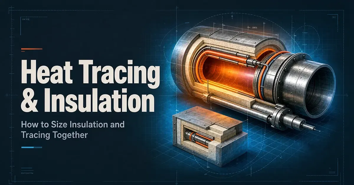
Most heat-tracing problems are insulation problems that were decided too late. The insulation is not a finishing layer chosen after the heater; it is the thermal boundary that sets the pipe's steady-state heat loss, and therefore the heater duty, the control authority, the steam circuit geometry, and the conditions under which corrosion under insulation develops.
One-sentence conclusion: define the insulation first, because everything downstream of it - tracer count, cable output, controller deadband, condensate load, inspection plan - is a consequence of the heat loss it allows.
Five rules run through this guide:
- The design object is a coupled thermal system, not a nominal thickness plus a heater added later. For a given process setpoint, fluid, pipe geometry, ambient envelope, wind, solar and rain exposure and allowable deviation, the model begins with linear heat loss q = (T process - T ambient) / R total, where the insulation resistance is cylindrical and the outer surface resistance includes convection and radiation.
- The 1.2-1.5 multiplier is an estimating convention, not a formula. The tracer has to replace the controlled-case loss plus startup, distribution and reliability allowances. A single factor is a useful check in a narrow early-feasibility model; it fails as a universal rule once steam pressure, wind, tracer-to-pipe contact, cable output curve, control deadband or circuit length dominate.
- Steam and electric tracing do not differ only in energy source. Saturated-steam duty is tied to a temperature plateau, pressure and condensate hydraulics, tracer-to-pipe contact and the coldest point on the circuit. Electric duty is tied to certified output at the relevant temperature, heater technology, controller and limiter architecture, circuit length and electrical protection.
- The construction detail inside the insulation decides the result. Grooved rigid sections, oversize bores, a compressed fibrous layer and a tracer hanging in an air annulus are four different thermal systems, even at the same nominal thickness.
- A traced line is not a self-drying asset. Cycling, outages, sub-dew-point operation, jacket breaches, soluble halides and poor drainage can recreate exactly the wet-warm-oxygen-crevice condition that corrosion-under-insulation programmes exist to prevent.
The rest of this guide works through the coupling, the two tracing technologies, the construction layer, the calcium silicate claim that circulates as a rule of thumb, corrosion risk, the honesty of published numbers, cold-start cases, verification and the specification language that holds it together.
1. The Coupled Design Starts With a Thermal Boundary, Not a Heater Catalogue Number
A useful heat-tracing design begins with a controlled thermal problem: hold a defined location on the process pipe inside a temperature band, for a stated load case. The heater is one actuator in that control problem. The insulation is the dominant passive constraint, and the method behind its thickness calculation - heat-loss, burn-protection, condensation or economic variants - is covered in our insulation thickness calculation guide.
For a single layer on a horizontal pipe, the linear resistance is
R insulation = ln(D outer / D inner) / (2 pi lambda at mean temperature)
q = (T pipe - T ambient) / (R insulation + R surface)
with the surface resistance
R surface = 1 / [(h convection + h radiation) x pi x D outer]
Here T pipe is not automatically the fluid setpoint. It is the pipe-wall temperature at the control location, which can sit below the bulk fluid during no-flow, stratified or heavily insulated conditions. The widely used calculation practice for radial, one-dimensional steady or quasi-steady heat flow in piping circuits warns that accuracy is extremely dependent on the accuracy of the input data, and the complementary industrial calculation framework requires the temperature dependence of thermal conductivity to be retained rather than replaced by a single brochure value.
Insulation thickness changes four things at once. First, a thicker annulus raises cylindrical conduction resistance, so steady heat loss normally falls. Second, it reduces the heater-to-pipe thermal coupling per unit contact area unless a cement, foil, clamp or compression strategy is changed. Third, it moves the outer surface closer to ambient, which helps personnel protection and rain-fire exposure but reduces the temperature head available to a steam tracer. Fourth, it changes cost, footprint, support loading, inspection access and the consequences of a wet or compressed layer. Adding 25 mm is therefore not an optimisation; it is a perturbation of a coupled system.
1.1 The design duty is the controlled-case loss, not the bare-pipe table
For procurement, write the required heater output as
Q design = q design x L equivalent + Q fittings + Q startup and margin
where L equivalent includes valves, flanges, supports and other localised losses if they are not separately traced or jacketed. The margin is then decomposed rather than guessed:
| Contribution | What it covers | How to establish it |
|---|---|---|
| Thermal-input uncertainty | Conductivity curve, jacket emittance, contact, construction tolerance | Sensitivity cases, not a fixed multiplier |
| Environmental severity | Lowest ambient, wind gusts, rain, solar, indoor draughts | Site meteorological and plant data |
| Process severity | No-flow hold, shutdown restart, batch cooling, turndown | Process hazard and operability cases |
| Distribution effect | Steam pressure drop and condensate, or cable voltage, current and length | Circuit calculation, not linear extrapolation |
| Reliability objective | Sensor or controller failure state, redundant zone, maintainability | Safety and availability requirements |
| Constructability loss | Compression, joint gaps, tracer sag, missing fittings | As-built inspection and test |
The common 1.2-1.5 multiplier is defensible only as an early estimating convention applied after the model already represents the real insulation geometry and the governing ambient case. It is not a substitute for a steam-tracer count, an electric-circuit power map, a freeze-risk assessment or a hazardous-area thermal classification. Applied to a bare-pipe loss it overstates what a well-insulated line needs; applied only to a cable nameplate output it understates a steam circuit whose condensate cannot clear.
Too thin is not merely a bit more kW. Undersizing insulation raises steady loss, so the heater runs longer or at a higher setpoint. That narrows control headroom, raises steam condensate or electrical energy, accelerates wear on control valves and contactors, and increases the penalty when the ambient model was optimistic. In a cold snap the line may cross the process limit before the controller can respond, particularly in no-flow hold.
Too thick is not free reliability. At some point the incremental loss reduction becomes small while the air gap, inner diameter or compression path changes. For steam, a larger insulation annulus can reduce the temperature difference between tracer and product, requiring more tracer tubes, higher steam pressure or a different coupling method. For electric systems, excessive thickness can mask local overheating if the cable is poorly contacted, make sensor response sluggish, and increase replacement labour. Thickness must be optimised against annualised energy, heater and control cost, material and labour, footprint, safety and maintainability - not picked from a single safe number.
2. A Joint Workflow Keeps the Insulation and Tracing Packages From Drifting Apart
The workflow below is the procurement-control mechanism. It converts a line list into a model, a construction specification, a test record and an operating envelope. In plant practice the same structure carries across units - distillation, cracking furnaces, tankage and traced services - which is why the petrochemical plant insulation guide uses the same decomposition, and why piping and process insulation applications are specified this way rather than from a product catalogue.
| Stage | Required outputs | Owner or checker | Gate |
|---|---|---|---|
| 0. Operating envelope | Process minimum and maximum temperature, hold time, viscosity or solidification curve, pressure, fluid hazards, cleaning and steam-out | Process and safety | No heater selected until the cases are signed |
| 1. Environmental envelope | Design low and high ambient, wind, rain, solar, indoor humidity, location, access, maintenance frequency | Piping, EHS, site meteorology | Not a single winter temperature |
| 2. Thermal model | Pipe outer diameter, insulation inner and outer diameter, conductivity curve, jacket, emissivity, surface coefficient, fittings, no-flow and startup cases | Piping and thermal engineer | Model and sensitivity cases registered |
| 3. Tracer concept | Steam: saturation table, pressure drop, trap and condensate, tracer count. Electric: type, output curve, voltage, length, zones | Tracing designer | Both options carry equal boundary conditions |
| 4. Control and safety | Sensor location, deadband, alarm, high-temperature limiter, fail state, hazardous-area compliance | Instrumentation and electrical | Setpoints traceable to heater approvals |
| 5. Mechanical interface | Bore, groove or oversize, contact, fixation, compression, expansion, jacket seals, labels | Piping and insulation contractor | Approved routing drawing and material data |
| 6. Corrosion and materials | Base metal, insulation chemistry, coating, weather barrier, drainage, inspection plan | Materials, corrosion and QA | Halogen and leachables compatibility accepted |
| 7. Economics | Installed capital, energy, steam and condensate losses, controls, maintenance, outage risk | Project controls and operations | Iteration stops on lifecycle value, not first cost |
| 8. Commissioning and as-built | Infrared or heat-flux survey, voltage, current and power, sensor calibration, continuity, loop test, photographs | Electrical, mechanical and QA | Deviations closed before handover |
The feedback loop is the product. If stage 3 raises steam pressure to solve a cold end, stage 2 must be rerun: jacket surface temperature, pipe hot-spot temperature, heater exposure rating and trap capacity may all change. If stage 5 moves from a grooved rigid section to an oversize fibrous bore with an air gap, the tracer-side heat-transfer coefficient changes and the previous heater count is invalid. If stage 6 moves to a stainless-compatible product, the conductivity curve and jacket system must be those of the purchased product, not the preliminary generic. A revision number has to follow this chain through the line list, the datasheets, the drawing and the test pack.
3. Steam Tracing Makes the Tracer a Distributed Heat Exchanger With a Hydraulic Constraint
Steam is attractive where a plant already has clean, reliable steam and a line needs robust freeze protection or a broad heat input. But the steam temperature is not a single number you assign to a pipe.
3.1 Saturation, pressure drop and the cold end govern the design
For saturated steam, temperature is a function of pressure at the inlet, and the tracer is also a condenser. The heat delivered locally depends on tracer surface temperature, condensate film, tracer-to-pipe contact, any heat-transfer compound, the insulation cavity and the process-side resistance. The designer therefore has to check five things:
- Inlet saturation condition - the pressure at the tracer supply, not merely the name of the utility header.
- Pressure and heat-drop profile - whether the tracer can hold the required temperature at the furthest, highest or most exposed point.
- Condensate removal - trap capacity, orientation, freeze protection, lift, discharge, and the consequences of failing open or closed.
- Tracer count and spacing - derived from local duty, not from a rule such as one 12 mm tube per DN.
- Thermal coupling - a tracer loose in air, cemented, clamped or deliberately isolated behaves differently in each case.
A steam tracer is not automatically isothermal. The supply condition may be stable, but heat loss along the run, pressure variation, non-condensable accumulation and poor drainage can make the end point the governing case. A control valve on the supply does not remove this, because it modulates an available temperature plateau rather than creating one. A low-pressure system can itself freeze in severe cold: published engineering specifications treat ambient below about -28.9 C (-20 F) as a low-pressure-steam freeze risk requiring freeze-resistant traps and protected condensate lines.
3.2 Insulation geometry must be recalculated after the tracer is placed
For rigid calcium silicate, expanded perlite, cellular glass and similar sectional products, a tracer occupies volume inside what was assumed to be an annular insulation layer. A published project specification describes the two routes: groove the rigid section longitudinally, or select the next larger nominal pipe insulation and accommodate the pipe-plus-tracer annulus. It then requires that heat loss be calculated with the actual selected insulation dimensions, and that the model state whether the assembly is compressed to fit or oversized with an air annulus. The calcium silicate product standard governs the material form and references dimensional practice for rigid sections; it does not give a universal groove-depth rule for every tracer size and contact method. The product-level view of calcium silicate pipe sections is a good starting point, but the routed cross-section still has to be approved for the actual assembly.
This is why a generic minimum remaining wall cannot be responsibly stated. Groove depth, width and residual thickness depend on the product's certified compressive and flexural strength, the tracer outside diameter and whether it is a tube, a pair or a jacketed bundle, the declared groove-manufacturing method and tolerances, the orientation and support locations, the intended contact or cement path, the outer-jacket load and anticipated traffic, and the air-gap resistance the thermal model actually assigns.
What can be specified without pretending to be the manufacturer: require the insulation vendor and the tracer vendor to co-sign the routed cross-section; define nominal and minimum local insulation thickness independently from the nominal bore; prohibit undocumented field cutting that leaves a thin web; and rerun the thermal model for the compressed, seated and worst-tolerance conditions. If the remaining local thickness is a project limit, derive it from the selected product's structural and thermal data rather than inventing an international constant.
4. Electric Tracing Makes Ratings, Output Curves and Control Architecture the Governing Constraints
Electric tracing removes the steam-header and condensate problem, but introduces a different coupling: the cable's certified thermal performance is a function of its own temperature and exposure history, while the circuit is constrained by voltage, length, current, protection and approvals.
4.1 Electric is not one technology
| Attribute | Self-regulating | Constant wattage or series longline | Mineral insulated |
|---|---|---|---|
| Output behaviour | Matrix resistance rises as it warms, so output varies along the length with local conditions | Designed for a specified output at rated conditions; circuit and length discipline is central | High-temperature capability and robust sheath construction in many designs; the exact rating is product-specific |
| Strength | Automatic local modulation for some freeze-protection and maintenance duties | Predictable output and long-circuit economy when properly designed | Compact, durable, suitable for high-temperature and hazardous-area use in qualified products |
| Design caution | The output curve still depends on ambient, process and exposure; do not treat it as a thermostat | Overlapping circuits, wrong voltage or length, or poor heat sinking can cause deviation | Sheath, mineral insulation, termination, bending and compaction must follow the maker's data |
| Procurement key | Certified maintenance and exposure temperatures, temperature class and approval, startup current | Nameplate output at a stated temperature, voltage, circuit length and connection method | Sheath compatibility, bending radius, compaction, termination and temperature class |
A single product example shows why generic temperatures are dangerous. One manufacturer's self-regulating product is offered at several power densities and lists a maximum maintenance temperature of 150 C at 110-277 VAC, but only 121 C at 380-480 VAC; its exposure limits also differ between energised and de-energised states and by voltage. Another series-construction family is advertised up to 60 W/m, which is a specific family limit, not an industry maximum. The procurement specification must obtain the actual datasheet, output curve, approval certificate, termination kit and installation manual before the insulation bore is frozen.
4.2 Control must be designed for the failure state
The current joint IEC and IEEE baseline for electrical resistance trace heating replaced its 2013 edition, harmonises with the equivalent IEEE standards, and adds control and monitoring provisions plus termination type-test requirements. The practical consequence for a buyer is that product selection and field installation cannot be separated from the control, monitoring and termination system that the certification assumes.
One further distinction matters. The commercial-application electrical trace-heating standard is scoped to potable and hot-water freeze protection, sprinkler systems, roof and gutter de-icing and similar duties; it is not a blanket industrial-process standard. Industrial process lines must also address the applicable national electrical code, hazardous-area equipment standards for explosive atmospheres, process safety, and the approval conditions of the heater and system. The common claim that one electrical standard covers all heat tracing is imprecise.
A thermostat is not enough merely because the cable is self-regulating. Define line or ambient sensing, controller versus mechanical thermostat, an independent high-temperature limiter where required, sensor drift and fault response, alarm and control-system visibility, ground-fault protection, and the required action on loss of power. The sensor must sit where the process is coldest or most difficult to heat, not where it is easiest to mount. On electric systems the controller sees cable and pipe state only indirectly, so commissioning has to confirm that a steady pipe temperature corresponds to the intended heater state.
5. Steam Versus Electric: The Insulation Consequences Differ Even When the W/m Looks Similar
| Decision axis | Steam tracing | Electric tracing | What the insulation specification must capture |
|---|---|---|---|
| Driving temperature | Saturation temperature at local pressure, a plateau rather than a fixed output | Certified output at product, process and exposure temperature and applied voltage | Do not transfer an output figure between technologies without rerunning the model |
| Along-run behaviour | Condensing profile, pressure drop, non-condensables, trap health | Voltage and current, circuit length, cable type, connection losses, local self-regulation | Cold-end check for steam; circuit-end, voltage-drop and overload checks for electric |
| Adjustment range | The valve modulates steam; the heat head falls as insulation thickens | Setpoint, duty cycle, limiter and the product output curve | Control authority and sensor location |
| Heat-transfer path | Tracer-to-pipe contact dominates; cement, clamp or air gap are material choices | Cable-to-pipe contact and local heat sinking dominate; no cement assumption by default | Groove, oversize, air gap, foil, clamps and compression each need a model and vendor approval |
| Failure mode | No steam, blocked or frozen trap, water hammer, overpressure, burn hazard | No power, sensor or controller fault, overtemperature, cable damage, ground fault | Redundancy, alarms, isolation, thermal imaging and post-work insulation-resistance testing |
| Utilities and maintenance | Steam supply, condensate return, traps, strainers, filtration | Power distribution, breakers, ground-fault protection, terminations, controllers | Lifecycle energy and maintenance entries must be technology-specific |
| Best early fit | Existing reliable steam, large or robust duties, where steam-out and cleaning are compatible | Tight temperature bands, remote runs, zoning, certified hazardous-area systems, no steam header | Stop at a total-cost-and-risk comparison, not at a heuristic |
Historical framing should stay in its era. A 1995 chemical-process-industries journal article reported that over 90 percent of industrial tracing was steam in the 1960s and that electric tracing had risen to over 30 percent by 1995. That is one journal's observation of one industry in one country, not a global census, not an installed base for 2026, and not evidence that either technology dominates today. It belongs in a lessons-learned note, never in a procurement claim about current market share.
6. The Layer Inside the Insulation Matters as Much as the Nominal Thickness
6.1 Rigid insulations: groove or oversize, then recalculate
For hard pipe sections a tracer may be placed in a longitudinal groove, or the assembly may move to the next nominal bore. The retrieved engineering specification supports this choice but adds the critical qualification: use the actual insulation dimensions in the heat-loss calculation, and state whether the product is compressed or left with an air annulus. It also requires expansion slots where the tracer joins or leaves the line, because that is where tracer and insulation movements and discontinuities occur.
No universal minimum remaining wall or groove-depth formula was found in the cited standards or in manufacturer-neutral engineering guidance. A design authority should therefore require a cross-section drawing with tracer outside diameter, insulation inner and outer diameter, groove width and depth, seat and clearances; the insulation vendor's certified dimensional tolerances, compressive load limits and recommended groove practice; the tracer vendor's permitted contact materials, heat-transfer compound compatibility and minimum bending and seating radii; a thermal model that includes the local air gap or compression rather than only the nominal thickness; a site instruction prohibiting ad-hoc hammering, shimming or double compression; and an as-built photograph and inspection note before the outer jacket closes. The broader construction options, including preformed sections, wrapped blanket and removable covers, are compared in pipe insulation construction types.
6.2 Fibrous mineral wool or glass wool: it nestles in is not a calculation
Soft fibrous products often accommodate a small tracer without a precision-machined groove, but the tracer must not be treated as thermally merged with the pipe. If the tube or cable sinks into the fibre, the local density rises, the declared conductivity may no longer represent the compressed tuft, and a heat-flow shortcut forms. Conversely, if it hangs in an oversize annulus, the gap changes convection and the contact resistance may be far higher than a seated assumption.
Use an oversize bore or a manufactured channel that is called out in the model. If a light fixing is used, specify four things: no compression to a hard spot, so the local fibre is not crushed to the pipe or jacket during banding; no thermal bridge, so straps, wires and foil do not create a continuous high-conductivity path from pipe to jacket unless that is a designed heat-transfer feature; stable routing, so the tracer cannot migrate, sag or become trapped in a shell joint; and manufacturer concurrence on the fibre product, jacket, temperature and any foil or cement combination. A published mineral-insulated cable manual warns against allowing insulation or other material to lodge between cable and pipe, because that causes localised overheating; it also forbids trapping the cable in the joint between half-shells and recommends a metal-foil cover in some cases. That is product and installation guidance, not general permission to embed any cable at any power density. For the material families themselves, see mineral wool pipe sections, the rock wool insulation overview and the wider comparison in industrial pipe insulation materials.
6.3 Electric cables usually need no groove, until power density, temperature or geometry says otherwise
A flat or round electric heater can often run directly on the pipe under a correctly sized half-shell. Grooving is not intrinsically required by that fact alone. But high sheath temperature, high output per metre, close parallel runs, spiralling, closed-cell foam, a fibrous product that compresses, or a manufacturer's qualified assembly may demand a channel, foil, spacing or fixation. The governing question is local heat flux and the path to the pipe, not whether the installer can push it in. Where clearance is the binding constraint, a thin aerogel blanket hot-face layer is sometimes used instead of a thicker fibrous build-up, provided the temperature limit and jacket performance are compatible.
| Interface item | Minimum engineering verification |
|---|---|
| Tracer or cable contact | Permitted contact materials, and whether pipe contact is required, optional or prohibited |
| Groove or channel | Vendor drawing, residual thickness, tolerance, seam and joint location, expansion break |
| Oversize bore | Actual inner and outer diameter, declared air-gap resistance, no unintended convection path |
| Fixation | Band or clip material, coating, spacing, tension limit, no cutting or crushing of fibre |
| Thermal bridge | Model or test of straps, foil, cement, cladding fasteners and pipe shoes |
| Jacket closure | Seals at tracer exits, sensor capillaries, valves and brackets, no sharp penetrations through cable |
| Marking | Traced-equipment labels at defined intervals and at valves and components, maintainable after cladding |
Binding pitch is not a free number. Manufacturer-neutral and vendor sources do not establish a globally valid strap spacing for all tracer types, insulation densities and orientations. State the fastener system, allowable surface load and maximum interval in the product-specific installation manual or on an engineered drawing. Where a source gives 2.5 m vertical baffle spacing or 3 m label spacing, treat those as that manual's instruction, not a transferable rule for all mineral wool, cables and jackets.
7. The Calcium Silicate 35-40 Percent Claim Is Not a General Design Factor
The contested statement - that when selecting calcium silicate from a mineral-wool or glass-wool heat-loss table, loss should be increased by 35-40 percent - could not be corroborated by a second, methodologically adequate public source. The only supporting-style material found was a supplier comparison that tied the claimed advantage to a low mean-temperature band, particular product grades and density and binder behaviour. It was not a product-independent standard or test regime.
Classification temperature and nominal density are not thermal-performance certificates. Two calcium silicate products can have different pore structures, binder systems, density grades and conductivity curves, and the same is true for rock wool, glass wool and multilayer systems. Apparent conductivity in a fibrous product changes with temperature, density, ageing, compression and moisture, and the recognised calculation practice requires the appropriate apparent conductivity rather than an assumption of pure conduction.
The defensible procurement rule is conditional:
- Obtain the purchased product's conductivity curve, test method and test conditions from the declared manufacturer data.
- Use the mean temperature consistent with the calculation method, and iterate if the outer surface temperature changes materially.
- Apply the actual inner and outer diameters, air gaps, compression, jackets, seams and supports.
- Run the candidate materials through the same model and the same worst-case ambient and wind cases.
- If a 35-40 percent sensitivity is used at all, label it as a what-if perturbation for one early comparison, not as a physical property of calcium silicate.
If plant history shows a 35-40 percent field difference, keep it as a site calibration observation and find the cause: wrong mean temperature, water ingress, lower density, a crushed section, different jacket emittance, or an air-gap model error. Do not embed an unverified multiplier in a global specification. The product-level guidance in our calcium silicate pipe insulation article follows the same principle: quote the curve, not the label.
8. A Traced Line Can Still Develop Corrosion Under Insulation
Corrosion under insulation is a system failure involving metal temperature, moisture, oxygen, contaminants, crevices, coating condition and time. Heat tracing changes the first variable and may keep a line above dew point during normal operation, but shutdowns, ambient swings, jacket damage, wash-down, rain ingress and cyclic condensation can re-establish the hazard.
Inspection guidance for insulated components is explicit on this point: inspection should focus on conditions including alternate wetting and drying where trace contaminants may be present, and on the time spent below the dew point. It also distinguishes intact, moisture-impermeable, tightly adhering insulation from the rest of the population - the former need not be stripped automatically if the moisture barrier is undamaged, though the exterior must still be inspected for barrier damage. The honest conclusion is measured: good weatherproofing and normal operation reduce probability, but they do not make the line a permanently dry zone. The jacketing and weather-barrier details that carry most of this risk are covered in pipe insulation cladding and weatherproofing.
8.1 Materials compatibility must be specified, not assumed from non-corrosive
For austenitic stainless steel, soluble chloride and fluoride species are a particular concern, because moisture can transport and concentrate them at the hot metal surface. The relevant specification framework for non-metallic thermal insulation in contact with austenitic stainless steel uses pre-production stress-corrosion testing plus production-control chemistry, and the accompanying laboratory test method determines water-leachable chloride, fluoride, silicate and sodium ions in the parts-per-million range. It is a test method, not a declaration that any measured value is automatically safe for every alloy, temperature and service.
Therefore: call out the base metal and the weld and crevice condition rather than simply stainless steel; require the insulation and all accessories - fill, cement, mastic, tape, jacket, sealant - to be compatible with that metal and service; specify leachable-ion testing and acceptance criteria in the project quality plan instead of copying a generic ppm limit without the alloy, extract and temperature rationale; and remember that halogens arrive from the environment as well as the product, through seawater spray, road salt, process leaks and contaminated wash water.
8.2 Corrosion control checklist for traced lines
| Layer | Design and contract requirement | Verification |
|---|---|---|
| Metal and coating | Identify the susceptible alloy family; specify under-insulation coating where the risk case requires it | Coating data, application records, holiday and visual check before insulation |
| Insulation chemistry | Purchase to a stainless-compatible specification; retain lot certificates and the leachable-ion test basis if specified | Lot traceability; quarantine non-conforming lots |
| Physical form | Avoid unnecessary continuous water paths; consider drainable, inspectable details at low points and penetrations | As-built drainage direction and low-point check |
| Jacket and seal | Closed, corrosion-resistant, UV and impact-appropriate jacket; sealed penetrations; sloped and continuous drainage | Water or hose test if specified; visual, fastener and seam check |
| Supports and shoes | Break capillary paths; avoid crevices that hide water; insulate and coat the support interface as designed | Mock-up and as-built photographs |
| Cycling and shutdown | Identify sub-dew-point transients, planned cleaning, steam-out and idle periods | Operating envelope review and inspection triggers |
| Inspection | Risk-rank the population; use exterior survey, targeted non-destructive examination and strip-out sampling rather than assuming traced equals dry | Registered inspection plan, findings trend, remediation loop |
| Maintenance | Repair the jacket immediately; label traced lines; train scaffolders and insulators on cable and seal damage | Work-pack controls and retest after strip and re-insulation |
9. Published Numbers Are Useful Only When Their Boundaries Stay Honest
9.1 The 311 W/m value is a source-specific bare-pipe value
A widely cited steam-engineering table gives an equivalent 311 W/m for a DN65 line at a 150 C steam-to-air difference. Its stated basis is bare horizontal pipe, ambient between 10 C and 21 C, still air, and steam at the listed pressure condition. That makes it an excellent sanity check for a bare-pipe model, but not a design value for a 50 mm insulated line. The same source illustrates insulation with a reduction factor - for example, that insulation reduces losses to 10 percent - rather than proving a particular thickness and material. Multiplying 311 by 0.1 to get 31.1 W/m is therefore a table-factor illustration, not a performance guarantee for rock wool.
9.2 The 669 to 111 W/m pair is unverified as a generic claim
The commonly circulated pair - a DN65 line at 300 C losing 669 W/m bare and 111 W/m under 50 mm of rock or mineral wool - could not be reproduced from a source that disclosed all of the DN definition, exact outer diameter, insulation inner and outer diameter, material conductivity curve, ambient, wind, emissivity, jacket, contact and calculation method. It is plausible as a particular model result, but it must not be used to select a heater or to claim an 83 percent reduction across projects.
9.3 Illustrative comparison: declare every input
| Case | Inputs | Result | Legitimate use |
|---|---|---|---|
| Source table | DN65, 150 C steam-to-air difference, bare, horizontal, ambient 10-21 C, still air | 311 W/m | Bare-pipe benchmark only |
| Article illustration | DN65 outer diameter 76.1 mm, 50 mm insulation, assigned conductivity 0.040 W/m K, surface coefficient 10 W/m2 K, pipe 150 C, ambient 20 C, still air | 38.4 W/m with a jacket near 26.6 C | Shows method and sensitivity, not a vendor rating |
| Commonly quoted 300 C pair | Stated as 669 to 111 W/m | Not independently replicated | Use only as project-source data with full inputs attached |
In the declared illustration, the 50 mm layer takes the loss from a calculated bare value of about 255 W/m to 38.4 W/m, an 85 percent reduction for those inputs. A different rock wool grade, wind speed or outer diameter changes that percentage. That is the point of publishing the inputs: anyone can change the conductivity, the surface coefficient, the diameter or the ambient and see that there is no universal thickness-to-savings curve. At a fixed 50 mm thickness, linear loss moves with both the assigned apparent conductivity and the outer-surface coefficient, which is why two sites with the same pipe and the same catalogue product can measure different losses.
9.4 Energy and cost arithmetic must not be done with thermal percentages
For an electric line, annual energy is approximately
E year = Q design x F run x t year / eta system
where F run is the fraction of time the heater actually delivers useful heat after control, and eta system captures distribution and control losses only where they are separately measured. For steam,
m steam = Q design / delta h (steam to condensate) + m loss, distribution
with condensate return, boiler efficiency, blowdown and steam-generation cost treated explicitly. A 10 percent cut in steady heat loss does not mean a 10 percent cut in fuel or electricity: the heater may already be cycling, the ambient may be milder than design for most of the year, distribution losses may dominate, or the line may spend much of its time shut down. Procurement energy models should use time-series ambient data and a controller model rather than scaling a peak load by operating hours. For indicative material and installed-cost ranges to feed that model, see the insulation material cost comparison.
10. Cold Snaps and Start-Stop Cycles Are Separate Load Cases, Not Fudge Factors
Steady maintain is not recovery. A line that holds temperature in a 5 C breeze may still fail after a weekend outage at -25 C, especially if the fluid is thixotropic, has a pour point, crystallisation kinetics or a permitted low-temperature soak. The model needs the actual post-shutdown temperature profile and fluid rheology; the acceptable warm-up time and the point at which irreversible damage or blockage occurs; the available steam pressure or electric inrush current and the controller response; the effect of valves, flanges, drains, low points and uninsulated appurtenances; and the maximum safe heater or sheath temperature during recovery.
For steam, a cold start may temporarily condense much more steam than steady hold, challenge the trap, and create water logging if slope and discharge are wrong. For electric systems, recovery may demand a higher short-term duty than a maintenance cable can provide; adding a separate heat-up cable, a different circuit strategy or a process change is then an engineering decision, not a thicker insulation blanket.
The cold-wave case should be bounded, not invented. Use site-validated extremes, wind history and the actual exposure class. If the plant safety case says maintain the product above 60 C for 30 minutes after loss of flow at -30 C with 15 m/s wind, that is the requirement. Insulation thickness, tracer count and control scheme are iterated until the coldest modelled node meets it - and document which node that is, because the middle of a long straight run is often not the governing location. A valve, a support, a dead leg or a circuit end usually is.
11. Verification Must Prove the Installed System, Not Just the Calculation
| Test | When | Method and acceptance basis | Why it matters |
|---|---|---|---|
| Model baseline | Before bid | Freeze all inputs, versions, conductivity curves, ambient cases and tolerances | Prevents identical-looking bids from using different physics |
| Pre-installation materials check | Before insulation | Trace cable or tube, insulation lot, coating, jacket and accessories against approved data | A wrong jacket or halogen content cannot be fixed by a setpoint |
| Pre-insulation electrical test | Before cover-up | Continuity, insulation resistance, grounding and cable identification per manufacturer and applicable standard | Catches crushed or mis-terminated cable before it is hidden |
| Thermal survey | Stabilised commissioning | Infrared survey of accessible jacket, supplemented by in-situ heat flux or embedded sensor checks at predetermined points | Detects cold spots, bridging, compressed zones and sensor bias |
| Electric power loop | Commissioning | Measure voltage, current and derived output at the actual stabilised temperature and length; compare with the approved output curve | Confirms circuit length, supply and thermal coupling |
| Steam loop | Commissioning | Supply pressure, trap operation, condensate discharge, cold-end temperature, slope and drainage | Confirms the condenser circuit, not just the inlet steam temperature |
| Control proof | Commissioning and periodic test | Force low and high conditions or use the approved test procedure; verify controller, limiter, alarms, control system and fail state | The heater can be correct while the safety logic is wrong |
| Post-insulation electrical test | After jacket closure | Repeat insulation resistance and continuity, inspect connections, retain the signed record | Cladding screws and seams are a common damage event |
| Corrosion condition survey | Turnaround or periodic by risk | Exterior jacket, moisture signs, targeted non-destructive examination, strip-out sampling where triggered | Heat tracing does not replace a corrosion programme |
| As-built update | Every intervention | Mark tracing route, sensor location, tracer count, insulation type and thickness, label status | A future strip-out must not become a blind dig |
Infrared thermography is useful for finding anomalies, but it measures an external temperature and is influenced by jacket emissivity, wind, solar load and hidden air gaps. The recognised calculation practice pairs modelling with infrared inspection and in-situ heat-flux measurement for operating-system evaluation. Use thermography to target investigations, then verify with approved contact sensors, heat flux or controlled exposure.
12. Common Specification Errors and the Correction That Prevents Rework
| Error | Why it fails | Correction |
|---|---|---|
| Pick the insulation thickness, then ask for enough trace | Ignores contact, air gap, wind, fittings and control | Run the coupled model; iterate insulation, tracer and control together |
| Apply 1.2-1.5 to every result | Mixes uncertainty, control and distribution into one unexplained multiplier | Use decomposed margins and sensitivity cases; reserve a factor for a defined estimating stage |
| Quote example maintain and withstand temperatures as universal grades | Ratings vary with voltage, cable family, energised state, termination and approval | Enter the exact datasheet values and certificate references |
| Use a bare-pipe table as the insulated heat loss | A bare horizontal still-air table omits the insulation system entirely | Model actual diameters, conductivity curve, surface coefficient, emissivity and jacket |
| Treat calcium silicate as 35-40 percent worse by default | No independent, product-neutral validation; it depends on grade and mean temperature | Use product curves and a same-case comparison; flag the percentage only as a what-if |
| Groove rigid insulation to a made-up depth | Structural integrity and the local thermal path become unknown | Obtain the vendor cross-section and tolerances; model compressed and air-gap cases |
| Let a soft wool tracer settle without rules | Compression and bridging alter conductivity and heater contact | Specify channel or oversize bore, density limits, fixation and no-crush rules |
| Assume traced means dry | Shutdown, jacket breach and cycling create condensation and halide concentration | Risk-rank corrosion, specify compatible materials, weather barrier, drainage and inspection |
| Compare steam and electric on fuel price alone | Omits traps, condensate, controls, circuit length, availability and maintenance | Use lifecycle cost on the same thermal and environmental cases |
| Test only at the sensor | The sensor may sit at a warm node while a valve or a circuit end is cold | Map worst-case nodes, fittings, ends and supports, then commission the whole loop |
13. Ten Questions to Settle Before Bid Day
1. Is the target a minimum maintain temperature or a recovery time? If it is recovery, specify the initial fluid temperature, the allowable warm-up curve, the flow state and the maximum safe surface temperature. A maintenance-duty heater may simply be the wrong tool.
2. Which node must be proven? Name the pipe section, valve, flange, dead leg, circuit end or support that controls. The sensor location and the procurement acceptance must refer to that node.
3. Are the ambient numbers design extremes or averages? Use a defined meteorological basis, a wind exposure class and an indoor or outdoor distinction. A single winter temperature is not enough if 25 m/s wind is possible.
4. Which conductivity curve goes into the model? Demand the temperature curve, test standard, product density and any moisture or ageing correction. Do not accept a single 0.04 value without a declared mean-temperature basis.
5. Is the rigid layer grooved, compressed or oversized? The drawing and the thermal model must say which. Groove geometry and residual local thickness require product-specific approval; do not invent a universal minimum.
6. What are the heater's real temperature limits? Record maximum maintenance temperature, maximum exposure temperature for energised and de-energised states, sheath, jacket and termination limits, and the certification conditions. Example numbers are not specifications.
7. What happens on loss of control? Define the safe failure state, the high-temperature limiter, the alarm, and whether process shutdown or an alternative heat source is required. This drives both insulation and heater selection.
8. How is corrosion prevented during shutdowns? Identify dew-point transients, cleaning and steam-out, coating, stainless-compatible insulation chemistry, jacket integrity, drainage and the inspection trigger. Traced is not an answer on its own.
9. How will the installed duty be accepted? Write the stabilised pipe-temperature map, the power or steam measurement, the infrared and heat-flux protocol, the electrical tests and the as-built documentation into the purchase order.
10. What does the lifecycle model actually compare? Use the same operating schedule and boundary for steam and electric: fuel or boiler house, condensate, traps, power, demand charges, controls, spare parts, outages, safety and re-insulation labour. The cheaper first cost is not the optimised system.
14. Minimum Specification Language
The following is a purchaser-oriented skeleton, not a substitute for project codes or a licensed design.
The Contractor shall design each traced line as a coupled thermal system. Insulation thickness, material conductivity curve, actual inner and outer diameters, tracer or cable routing, contact and air-gap conditions, jacket properties, fittings, supports, ambient envelope and control strategy shall be entered into a documented steady-state model and, where startup or transients govern, a transient analysis. Tabulated bare-pipe heat losses shall not be substituted for the insulated-line duty. All heater outputs, maintenance temperatures, exposure temperatures, power density, circuit length, terminations and approvals shall be taken from the approved manufacturer data sheet and the certification applicable to the installed configuration.
For rigid insulation, any groove, compression, oversize bore or air annulus shall be shown on the approved cross-section, and the heat-loss calculation shall use the actual installed dimensions and tolerances. The insulation and tracer vendors shall jointly confirm the routed assembly. For fibrous insulation, the tracer shall neither be crushed into a local thermal bridge nor be free to migrate or become trapped in a shell joint; the fixation and channel method shall be manufacturer-approved.
The corrosion-prevention specification shall address base metal and welds, under-insulation coating where required, insulation and accessory leachable-ion and compatibility requirements, jacket continuity and drainage, penetrations, low points, cyclic and shutdown condensation, and the inspection and remediation plan. Traced status shall not be interpreted as immunity from corrosion under insulation.
Commissioning shall demonstrate the coldest controlled node, the fittings and circuit ends as applicable, stabilised heater duty, controller and independent protective functions, and post-insulation integrity. As-built drawings, material certificates, test records and thermal survey results shall be delivered before final acceptance.
Key Takeaways
- Insulation is the input to the tracing design, not a finishing decision made after the heater is chosen.
- The heater replaces the controlled-case heat loss plus decomposed allowances; a single 1.2-1.5 multiplier is an estimating convention, not a design rule.
- Grooved rigid sections, oversize rigid sections, compressed fibrous wool and a tracer in an air gap are four different thermal systems at the same nominal thickness.
- Steam tracing is bounded by a temperature plateau and by condensate hydraulics; electric tracing is bounded by certified output, circuit length and control architecture.
- Traced lines still corrode. Heat is a condition, not a guarantee of dryness, and shutdown cycling is where the risk concentrates.
- Published bare-pipe and insulated heat-loss figures are only usable when their full input basis travels with them.
- Verification has to prove the coldest node, the fittings, the control logic and the post-insulation integrity - not just the steady-state calculation.
Frequently asked
Does heat tracing replace insulation? +
No, and the two are not interchangeable. Tracing supplies the heat a line loses through its insulation. Without insulation, the heater would have to replace the bare-pipe loss, which is roughly an order of magnitude larger, and the temperature profile along the run would be impossible to control. Insulation reduces the duty; tracing makes up the remainder.
How thick should insulation be on a heat-traced pipe? +
It is set by the controlled-case heat loss, not by a standard number. Build the thermal model with the actual diameters, conductivity curve, ambient and wind case, then iterate thickness against energy cost, tracer capacity and surface temperature. Many industrial steam mains land in the 50-100 mm band, and 50 mm is a common floor for DN50 to DN200 lines, but each line still needs its own check.
Can you over-insulate a heat-traced line? +
Yes, especially with steam. A thicker annulus lowers steady heat loss but also lowers the temperature difference between tracer and pipe, so more tracer tubes or higher steam pressure may be needed to deliver the same duty. It also slows sensor response, increases replacement labour, and can hide a poorly contacted cable. Thickness has an optimum, not a maximum.
Do you need a groove in calcium silicate for the tracer? +
Either groove the rigid section longitudinally or move to the next larger nominal bore, and show whichever you choose on the approved cross-section. The heat-loss calculation must then use the actual installed dimensions and state whether the assembly is compressed or left with an air annulus. No standard gives a universal groove depth, so the insulation and tracer vendors should co-sign the routed assembly.
Can mineral wool simply close over the tracer? +
It will physically, but closing over is not a calculation. If the tracer sinks into the fibre, local density rises and the declared conductivity no longer represents the compressed tuft; if it hangs in an oversize annulus, the air gap changes convection and contact resistance. Call out a channel or an oversize bore in the model and prohibit crushing the fibre to a hard spot during banding.
Do electric heat tracing cables need a grooved insulation section? +
Usually not. A flat or round cable can often run directly on the pipe under a correctly sized half-shell, because it is thin compared with a steam tracer tube. Grooving or spacing becomes necessary at high sheath temperature, high output per metre, close parallel runs, spiralling, compressible fibrous products, or where the manufacturer's qualified assembly calls for it.
Steam tracing or electric tracing - which needs more insulation? +
Neither is intrinsically thirstier, but they fail differently. Steam depends on a saturation plateau that falls away along the run and at the cold end, so the design is checked at the furthest and most exposed point. Electric depends on certified output at the actual pipe temperature, voltage and circuit length, so it is checked at the circuit end and against voltage drop.
Why does insulation on traced lines get wet? +
Because tracing raises metal temperature but does not remove water. Shutdowns and ambient swings drop the line below dew point, jacket breaches and unsealed penetrations admit rain or wash water, and condensate accumulates at low points. A wet layer has a much higher apparent conductivity, so the installed heater capacity no longer covers the loss and the line can freeze while the controller reads normal.
Is heat tracing a corrosion-under-insulation control measure? +
No. Keeping a line warm during normal running reduces the time spent below dew point, but corrosion under insulation is a system failure involving moisture, oxygen, contaminants, crevices, coating condition and time. Shutdown cycling, wash-down and jacket damage re-establish wet-dry cycles. Traced lines need their own risk ranking, compatible insulation chemistry, sealed jacketing, drainage and inspection plan.
What is the 1.2 to 1.5 multiplier actually for? +
It is an early estimating convention, not a code formula. It bundles thermal-input uncertainty, environmental severity, process cases, distribution effects, reliability objectives and construction losses into one number. Once the model represents real geometry and the governing ambient case, replace the multiplier with a decomposed margin and sensitivity cases, or it will hide whichever term is actually large.
How do you verify the installed duty of a traced line? +
Prove four things: the coldest controlled node reaches its band, the fittings and circuit ends are not cold, the measured power or steam flow matches the approved output at stabilised conditions, and the controller and independent limiter behave correctly on forced low and high tests. Add post-insulation electrical tests, because cladding screws and seams are a common damage event.
Request a quote
Interested in our insulation solutions? Send us your requirements and our team responds within one business day.