
Power Plant Insulation: Materials & Thickness by System
How to specify power plant insulation by system — boiler, steam piping, turbine and HRSG — with recommended material and thickness based on operating temperature.
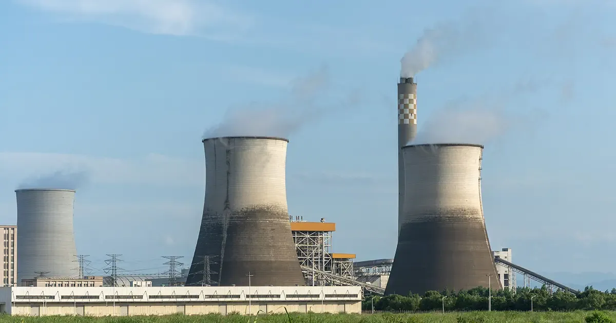
Why Power Plant Insulation Matters
In a thermal or combined cycle power plant, an estimated 5–10% of thermal energy escapes through the surfaces of boilers, pipes, and equipment. Good insulation is not a finishing touch — it is a core part of the plant's heat balance, safety envelope, and operating cost.
Three things drive specification:
- Fuel efficiency — every watt lost through a bare surface is fuel burned for nothing.
- Personnel safety — codes typically limit exposed surfaces to roughly 50–60°C (or about 25°C above ambient for turbine and boiler casing) to prevent burns.
- Equipment life — stable surface temperatures reduce thermal cycling, corrosion under insulation, and fatigue on rotating equipment.
For a full map of where these materials fit across the plant, see our power generation insulation applications overview.
How Insulation Thickness Is Determined
Thickness is rarely a guess. Most plants size it with the economic thickness method: the point where further added insulation costs more than the energy it saves over the asset's life. Two constraints usually cap the result:
- Maximum allowable heat loss — common design limits fall around 110–130 W/m² for hot piping.
- Surface temperature limit — typically ≤ 50–60°C on accessible surfaces.
Higher operating temperature, larger diameter, and a lower thermal conductivity all push the economic thickness upward. The tables below translate that into practical ranges for each system.
Insulation by Power Plant System
Boiler and Furnace Linings
The furnace enclosure runs hottest — flame and radiant zones reach 800–1100°C, with flue gas at 400–600°C across the economizer, superheater, and reheater.
- Radiant walls and arches (above 800°C): ceramic fiber blanket at 128 kg/m³, typically 50–100 mm, valued for very low heat capacity and excellent thermal-shock resistance during frequent start-stop cycles.
- Economizer and superheater sections (400–800°C): a composite of ceramic fiber plus calcium silicate board (total 150–200 mm) balances low conductivity against the mechanical strength needed for casing and support.
Steam and Feedwater Piping
- Main and hot-reheat steam (350–540°C): ceramic fiber + calcium silicate composite, 150–200 mm, to hold surface temperature and heat loss within code.
- Feedwater and low-temperature steam (150–250°C): rock wool blanket or glass wool, 80–120 mm — rock wool's higher density suits outdoor and mechanically exposed runs.
- Hydrogen-cooled generator piping (~ -40°C): high-density rock wool or ceramic fiber, 100–120 mm, with a non-combustible outer jacket for the explosive-atmosphere requirement.
Turbines and Rotating Equipment
Turbines add a vibration constraint. Specifiers favor flexible ceramic fiber or rock wool (80–100 mm) with stainless pinning at ≤ 250 mm spacing, so the lining stays put through decades of cyclic loading. Turbine casing surfaces are typically held within ~25°C of ambient.
Combined Cycle and HRSG
In a combined cycle plant, the heat recovery steam generator (HRSG) sees gas-turbine exhaust at 400–600°C. The casing, ducts, and stack are insulated with ceramic fiber blanket or a ceramic-fiber/calcium-silicate composite, while the HRSG steam piping follows the same 150–200 mm composite rule as the main steam line. Gas-turbine exhaust ducting often uses ceramic fiber modules for fast cyclic response.
Recommended Thickness by Temperature Range
| Operating temperature | Recommended material | Density (kg/m³) | Conductivity (W/m·K) | Typical thickness | Common systems |
|---|---|---|---|---|---|
| > 800°C | Ceramic fiber blanket | 128 | 0.045–0.060 @200°C; 0.152–0.200 @600°C | 50–100 mm | Boiler wall, superheater, reheater |
| 400–800°C | Ceramic fiber + calcium silicate | 128 / 220 | ~0.052 / ~0.060 @350°C | 150–200 mm | Economizer, main steam |
| 250–400°C | Ceramic fiber | 128 | ~0.052 @350°C | 80–120 mm | Mid-temp steam, feedwater |
| 150–250°C | Glass wool or rock wool | 48 / 120 | 0.040 / 0.045 @250°C | 80–120 mm | Low-temp steam, feedwater |
| < 150°C | Microporous (aerogel) or glass wool | 200 / 48 | 0.021 / 0.034 @25°C | 30–50 / 50–80 mm | Low-temp water, trace heating |
| Special (vibration, explosive atm.) | Ceramic fiber or high-density rock wool | 128 / 160 | 0.060 / 0.050 @400°C | 100–120 mm | Hydrogen-cooled piping, turbines |
Material Selection by Site Condition
- Vibration (turbines, compressors): flexible ceramic fiber or rock wool with pinned, multi-layer construction.
- Wet or outdoor service: choose hydrophobic options — microporous boards reach ≥ 99% water repellency; rock wool is naturally hydrophobic.
- High temperature and pressure: ceramic fiber blanket, or the ceramic-fiber/calcium-silicate composite where casing strength matters.
Energy Savings and Payback
The payoff is direct. On a 400°C steam line, moving from a thin, degraded layer to the ~150 mm economic thickness typically cuts surface heat loss from roughly 550 W/m² toward 300 W/m² — on the order of 150,000–200,000 kWh saved per year on a single line. Because insulation is cheap relative to fuel and the equipment it protects, payback on well-specified power-plant insulation commonly lands well inside the plant's operating life.
Regular inspection matters: a damaged or compressed layer loses far more than its rated value, so a scheduled check-and-repair program protects both efficiency and safety.
Explore flexible aerogel and microporous insulation options in our aerogel insulation guide.
Frequently asked
What is the best insulation for power plant piping? +
It depends on temperature. Main and reheat steam lines (350–540°C) use a ceramic fiber + calcium silicate composite at 150–200 mm. Feedwater and low-temperature lines (150–250°C) use rock wool or glass wool at 80–120 mm. Always size by the economic-thickness method and check surface-temperature limits.
How thick should boiler insulation be? +
Radiant walls and arches above 800°C typically use ceramic fiber blanket at 50–100 mm. Economizer and superheater sections at 400–800°C use a ceramic-fiber/calcium-silicate composite of 150–200 mm to meet heat-loss and surface-temperature codes.
What insulation is used in combined cycle HRSG? +
HRSG casing, ducts, and stacks see gas-turbine exhaust at 400–600°C and are insulated with ceramic fiber blanket or a ceramic-fiber/calcium-silicate composite. The HRSG steam piping follows the same 150–200 mm composite rule as the main steam line.
How is insulation thickness calculated? +
Most plants use the economic thickness method — the thickness where added insulation costs more than the energy it saves. The result is capped by maximum allowable heat loss (around 110–130 W/m² for hot piping) and a surface-temperature limit of roughly 50–60°C.
Which insulation handles vibration on turbines? +
Flexible ceramic fiber or rock wool, 80–100 mm, pinned with stainless hardware at ≤ 250 mm spacing. Multi-layer construction resists fatigue and keeps the lining stable through decades of cyclic loading.
Request a quote
Interested in our insulation solutions? Send us your requirements and our team responds within one business day.