
Microporous Insulation Back-Up Layer: How Thick, and When It Fails
A microporous back-up layer is bounded on both sides. Worked multi-layer numbers, the interface-temperature trap, and the acceptance clauses that keep it inside its limit.
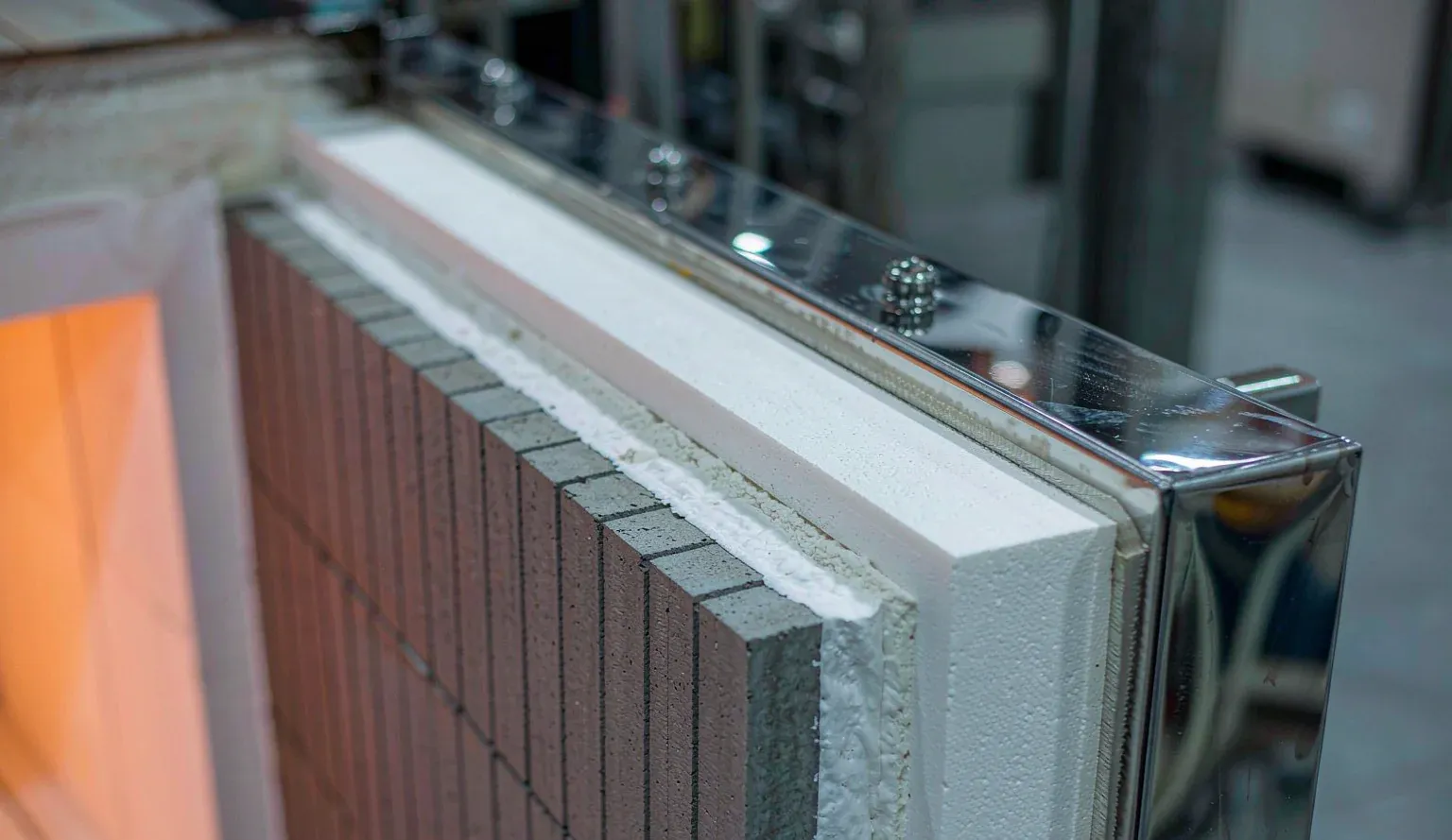
Every furnace lining specification contains a thickness for the back-up layer, and almost every one of those numbers is a minimum. The shell must stay below a limit, so the insulation must be at least this thick. That is the half of the problem that gets calculated.
The other half has no number in the specification, and it is the half that decides whether the layer survives its first campaign. A back-up layer also has a ceiling, because the same board that keeps heat out of the shell is standing between the hot face and everything behind it. Make it thicker and it runs hotter. There is a window, and in some linings the window does not exist at all.
This page works through that window with one consistent model, states every assumption, and shows where the arithmetic stops supporting the usual rule of thumb.
What this page does and does not claim
The worked examples use representative constant conductivity values for the refractory and fibre layers, and a single design-equivalent curve for the microporous board. Every input is listed in one table. The outputs are design-direction numbers that show which way the physics pushes and how large the effect is. They are not product data, and they are not a substitute for a project calculation.
Where a statement depends on a single source, it is labelled. Where a widely repeated industry claim could not be traced to a primary document, it is labelled as unverified rather than quietly repeated. ISO 18959 specifies product characteristics, test procedures and conformity assessment for rigid microporous products; it does not set the performance level required in any application, and the standard says so itself.
1. The short answer
The feasible thickness of a microporous back-up layer is squeezed from both ends. From the cold side comes a floor: shell temperature, heat loss and personnel protection all demand enough total resistance. From the hot side comes a ceiling: the board, its facing, its adhesive and its fixings have a continuous service limit, and they are sitting at the interface between the working lining and the back-up layer.
Adding board thickness lowers the shell temperature and raises the interface temperature at the same time. Those two effects are the same heat flux seen from two sides, so they cannot be optimised separately, and they move in opposite directions.
In a 1200 °C furnace with a microporous board placed directly against 150 mm of high-alumina brick, the window does not exist at any thickness. Every thickness from 20 mm to 60 mm puts the interface above the continuous limit, and thinning the board rescues the interface only by driving the shell above 300 °C. The structure itself is wrong, not the number. The fix is a fibre transition layer, which raises the resistance ahead of the board and pushes the interface down by several hundred kelvin.
2. Why the ceiling comes from the hot side
It is worth separating the two constraints because they come from different places and are written by different people.
The floor is written by the process and safety side. A shell temperature limit, a heat loss limit in W/m², a touch-temperature requirement, or an energy target all translate into a maximum acceptable heat flux, and therefore into a minimum total resistance. Thinner board means more heat flux and a hotter shell. That constraint is familiar and it is the one that gets specified.
The ceiling is written by the material side, and it is often left out. The interface temperature is not set by the board's conductivity. It is set by how much temperature drop the layers ahead of the board can absorb:
Tint = Thot − q × Rpre
where Rpre is the series resistance of everything between the hot face and the front face of the board. Adding board thickness increases the total resistance, which reduces q, which reduces the product q × Rpre, which raises Tint. The board's own conductivity enters only indirectly, through q.
Written as two inequalities, the geometry of the problem becomes visible:
- Interface limit: Tint must stay at or below Tint,lim, which requires q at or above a minimum q, which caps thickness from above.
- Shell limit: Tshell must stay at or below Tshell,lim, which requires q at or below a maximum q, which caps thickness from below.
A window exists only when the minimum heat flux demanded by the interface is lower than the maximum heat flux permitted by the shell. Substituting the two expressions gives a single test that can be run before any thickness is chosen:
h × Rpre must be greater than (Thot − Tint,lim) divided by (Tshell,lim − Tamb)
where h is the external surface heat transfer coefficient. For a 1200 °C hot face, a 1000 °C interface limit, a shell limit of 80 °C and an ambient of 25 °C, the right-hand side is 200 divided by 55, or 3.64. A lining with 150 mm of brick and no transition layer has h × Rpre of 0.79 — five times too low. A lining with 25 mm of fibre ahead of the board reaches 5.0 and passes.
This is also the clearest way to explain what a transition layer actually does. It is not extra insulation. It is a way of increasing Rpre so that the interface constraint stops binding, which is what turns an empty window into a real one.
3. The one number to calculate first: interface temperature
The temptation is to start from a conductivity value and a target resistance. That order is wrong, because the quantity that fails first is not the resistance, it is the interface temperature.
For a steady one-dimensional wall with layers in series, ignoring the steel shell's own resistance because it is negligible compared with the insulation:
- q = (Thot − Tamb) divided by (Rpre + t divided by λ + 1 divided by h)
- Tint = Thot − q × Rpre
- Tshell = Tamb + q divided by h
- the mean temperature of the board layer is approximately (Tint + Tshell) divided by 2, and λ is evaluated there
The order of operations that follows from this is: fix Rpre, check Tint against the limit, and only then choose board thickness. Any calculation that starts with "0.023 W/(m·K), therefore 40 mm" has skipped the step that decides feasibility.
There is one further consequence that catches people out. λ depends on the mean temperature of the layer, and the mean temperature depends on the solution. A single pass through the equations gives a wrong answer in both directions at once, so the calculation has to be iterated to convergence, not corrected with a margin.
Table 1 lists every input used in the worked examples on this page.
| Item | Value | Note |
|---|---|---|
| Hot face temperature, Thot | 1200 °C | Common for a reheating or heat-treatment furnace hot face |
| Ambient, Tamb | 25 °C | Still air, indoor |
| Working lining | 150 mm high-alumina brick, k = 1.8 W/(m·K) | Equivalent value at the layer mean temperature |
| Transition layer | 0 to 62.5 mm fibre, k = 0.15 W/(m·K) | Equivalent value at the layer mean temperature; zero in case A |
| Board conductivity | λ = 0.0261 + 0.000028 × Tm, W/(m·K), with Tm the layer mean temperature in °C | Design-equivalent curve; see the note below |
| Surface coefficient, h | 9.45 or 20 W/(m²·K) as stated | Project parameter, not a material constant |
| Steel shell resistance | Neglected | Justified by the ratio of thickness to conductivity |
The board curve used here gives 0.0317 W/(m·K) at 200 °C, 0.0407 at 521 °C and 0.0485 at 800 °C. It is deliberately higher than the bare-core values quoted on most datasheets, because it carries allowances for joints, fixing bridges, compression and ageing. It does not correspond to any specific product. A real project must replace it with the supplier's measured curve at mean temperature and list the allowances separately, which is the point of clauses 2 and 3 in section 14.
The surface coefficient deserves the same warning. It depends on emissivity, wind speed, orientation and neighbouring hot surfaces, and above roughly 100 °C radiation carries a large share of the loss. Using a single value such as 10 W/(m²·K) as a universal constant is a habit, not a design method, and the cases below therefore carry different values rather than being forced onto one.
4. The three-layer resistance network, worked
It helps to see the network once in full before looking at the thickness tables, because the same five terms reappear in every case.
The example below is case B at 40 mm of board: 150 mm brick, 25 mm fibre, 40 mm board, 1175 K of driving temperature difference.
| Term | Expression | Value | Comment |
|---|---|---|---|
| Working lining, R1 | 0.150 divided by 1.8 | 0.0833 m²·K/W | High-alumina brick at its mean temperature |
| Transition layer, R2 | 0.025 divided by 0.15 | 0.1667 m²·K/W | Fibre; this term is zero in case A |
| Rpre | R1 + R2 | 0.2500 m²·K/W | The only quantity that sets the interface temperature |
| Board, Rboard | 0.040 divided by 0.0407 | 0.9824 m²·K/W | λ must be iterated, see below |
| Surface film, Rs | 1 divided by 20 | 0.0500 m²·K/W | Convection plus radiation |
| Total, ΣR | Rpre + Rboard + Rs | 1.2824 m²·K/W | |
| Heat flux, q | 1175 divided by 1.2824 | 916 W/m² | Identical in every layer |
| Interface temperature | 1200 − 916 × 0.25 | 971 °C | Only 4 K below the 975 °C control value |
| Shell temperature | 25 + 916 divided by 20 | 70.8 °C |
The convergence path matters more than it looks. Starting from a single 200 °C conductivity value, the first pass gives 753 W/m², an interface of 1012 °C and a shell of 62.6 °C. After four passes the same structure gives 908 W/m², 973 °C and 70.4 °C. After eight it settles at 916 W/m², 971 °C and 70.8 °C.
Between the first pass and the converged answer, the interface falls by about 41 K while the shell rises by about 8 K. A single-pass calculation is therefore not conservative. It is wrong in one direction on one face of the wall and wrong in the other direction on the other face, and a margin applied on top of it is a margin against an error of unknown size.
5. Conductivity is quoted at mean temperature, not at one temperature
Datasheets for rigid microporous boards almost always list conductivity at a series of mean temperatures rather than as a single constant, and they say so in the column heading. A typical grade runs from about 0.022 W/(m·K) at 200 °C mean to about 0.034 W/(m·K) at 800 °C mean, measured by the guarded hot plate or heat flow meter method. Hydrophobic variants are tabulated the same way, at 200, 400, 600 and 800 °C.
The number "0.023 W/(m·K)" on a datasheet is therefore a measurement point, not a property of the material at every temperature. Treating it as a constant for the whole layer is equivalent to assuming the hot face of the board is at 200 °C, which it is not.
Table 3 quantifies the cost of that assumption on case B, where the design requires a board resistance of about 0.98 m²·K/W.
| Basis | λ used, W/(m·K) | Board thickness for the target resistance | Heat flux, W/m² | Shell, °C | Interface, °C |
|---|---|---|---|---|---|
| Datasheet value at 200 °C mean, used as a constant | 0.0317 | 31 mm | 1094 | 79.7 | 927 |
| λ iterated at the actual mean of about 500 °C | 0.0402 | 40 mm | 916 | 70.8 | 971 |
The under-sizing is 22 % in thickness and about 19 % in heat flux. On this case the shell misses its target by roughly 9 K, which is the difference between passing and failing an acceptance measurement. Note the direction of the interface error: the thinner board leaves the interface about 44 K cooler, so the interface looks healthier exactly while the shell acceptance is failing. A designer watching only the interface would conclude the lining is safe.
There is a related trap in how the tables are labelled. A blanket statement that all specified data are mean values may refer to a mean of production batches, not to a value measured at the layer mean temperature. The two mean values are unrelated. The reliable test is whether the table has a temperature column or a mean-temperature heading, not whether the word mean appears.
The exact specimen definition and mean-temperature procedure sit in the body of the test standards, which are not public. This page does not paraphrase web summaries as clause text.
6. Three temperature labels, and the weakest component rule
Most of the confusion around microporous boards comes from three different numbers wearing the same units.
| Label | What it means | Typical value for a rigid microporous grade |
|---|---|---|
| Continuous application temperature | The long-term service limit under sustained load and temperature | 950 to 1000 °C |
| Classification temperature | A grade label defined by an agreed shrinkage criterion, commonly linear shrinkage below 2 % after a 24 h soak; it is not a licence to run at that temperature | 1000 to 1050 °C |
| Peak temperature | Short-term capability, frequently for fire protection duty with a stated duration | 1200 °C, often limited to about 4 h |
A datasheet headline of "1200 °C" therefore needs one follow-up question before it goes into a purchase order: which label is that? A grade that states a continuous limit of 1000 °C, a classification temperature of 1050 °C and a peak of 1200 °C for up to 4 h is not a 1200 °C material, and using it at 1200 °C continuously is outside its declared envelope regardless of what the marketing line says.
The second half of this section is the rule that is most often missed. The limit of the back-up layer is the limit of its weakest component, not the limit of the core board.
| Component | Typical continuous limit | Consequence if overlooked |
|---|---|---|
| Microporous core | 950 to 1000 °C | The headline figure everyone designs to |
| Aluminium foil facing | About 500 °C | Facing burns away; the assembly is a 500 °C component with a 1000 °C core |
| E-glass cloth facing | About 500 °C | Same failure, different material |
| High-strength S-glass cloth | About 700 °C | Raises the ceiling, at a cost |
| Silica cloth | About 1000 °C | Only facing that does not de-rate the core |
| Adhesive or binder | Grade specific, often well below the core | Failure appears as delamination, not as a burned board |
| Fixings and anchors | Grade specific; metal fixings also short-circuit resistance | Local hot spots and an interface calculation that no longer holds |
A back-up layer built from a 1000 °C core with a 500 °C foil facing is a 500 °C assembly. If the interface is at 900 °C, that assembly is out of specification on the day it is installed, and no amount of thickness changes it.
7. ISO 18959: what the product standard does and does not decide
The product standard for rigid microporous thermal insulation for industrial use is ISO 18959, first edition published in September 2025, covering surfaces from 100 °C to 1150 °C for board and pipe sections. Several points in it are routinely overstated, so they are worth stating plainly.
| Assertion seen in circulation | What the source actually says |
|---|---|
| It covers 100 to 1150 °C | Correct. The scope is thermal insulation of industrial applications on surfaces from 100 °C to 1150 °C |
| "It does not specify the performance level required in an application" | Correct, and it is in the scope. Levels required for a given application are to be found in regulations or non-conflicting standards |
| The 1150 °C figure is a product temperature rating | Incorrect. It is the range of the standard. It is not permission to run a board at 1150 °C, and it is not a rating for any particular grade |
| It tells you what thickness to use | No. It specifies product characteristics, test methods, conformity assessment, marking and labelling |
| The 2025 edition is current and stable | Current, and already in revision. The second edition was registered as a new project in September 2026 and is under development |
Two consequences follow. First, compliance with a product standard is not evidence that a lining design is adequate, and no supplier should be asked to warrant an application-level outcome that the standard deliberately leaves to the specifier. Second, the existence of a product standard is exactly why the interface calculation cannot be skipped: the standard defines what the board is, and the project has to define what the board must survive.
There is also a lower bound worth remembering. The standard's range starts at 100 °C, which is a reminder that nanoporous material is a solution for a particular band of industrial problems, not an upgrade that every insulation layer should receive. Section 15 returns to that.
8. Worked case A: board directly behind the brick, the feasible range is empty
This is the arrangement that gets drawn when the drawing shows "microporous board, 40 mm" immediately behind the working lining, with no transition layer. Rpre is 0.0833 m²·K/W and the surface coefficient is 9.45 W/(m²·K).
| Board thickness, mm | λ at the converged mean, W/(m·K) | Heat flux, W/m² | Interface, °C | Shell, °C | Verdict |
|---|---|---|---|---|---|
| 20 | 0.0439 | 1821 | 1048 | 218 | Interface over limit, shell over limit |
| 30 | 0.0437 | 1342 | 1088 | 167 | Both over limit |
| 40 | 0.0436 | 1062 | 1112 | 137 | Both over limit |
| 50 | 0.0436 | 879 | 1127 | 118 | Both over limit |
| 60 | 0.0435 | 749 | 1138 | 104 | Both over limit |
Not one thickness puts the interface at or below 1000 °C, and the trend runs the wrong way: going from 20 mm to 60 mm raises the interface from 1048 °C to 1138 °C while dropping the shell from 218 °C to 104 °C. The two curves do not cross anywhere in the useful range.
The obvious response is to thin the board. At 10 mm the interface does fall to about 964 °C, inside the limit, but the shell is then at roughly 324 °C and the heat flux is around 2800 W/m². The working lining is no longer doing its job, and the shell is hot enough to be a personnel hazard and a heat loss problem.
The correct reading is not "choose thinner". It is that the two constraints have no overlap. The interface limit demands a heat flux of at least about 2400 W/m², while an 80 °C shell limits the heat flux to about 520 W/m². The two requirements are a factor of nearly five apart. No board thickness, no grade and no facing reconciles them, because the conflict is in Rpre, not in the board.
In a 1200 °C furnace, a microporous board placed directly against the working lining is therefore running above its limit by design, whatever number is written on the drawing.
9. Worked case B: with a fibre transition layer, a 25 to 40 mm window
Insert 25 mm of fibre between the brick and the board and Rpre rises from 0.0833 to 0.2500 m²·K/W. The surface coefficient is taken as 20 W/(m²·K), which corresponds to a lining with a substantial radiative component, and the control values are an interface at or below 975 °C, which is the 1000 °C continuous limit with 25 K held back, and a shell at or below 88 °C.
| Board thickness, mm | λ at the converged mean, W/(m·K) | Heat flux, W/m² | Interface, °C | Shell, °C | Verdict |
|---|---|---|---|---|---|
| 20 | 0.0392 | 1451 | 837 | 97.5 | Shell over 88 °C, below the window |
| 25 | 0.0397 | 1265 | 884 | 88.2 | Lower edge of the window; 91 K of interface margin |
| 30 | 0.0401 | 1122 | 920 | 81.1 | Inside the window |
| 40 | 0.0407 | 916 | 971 | 70.8 | Upper edge; 4 K to the control value, 29 K to the absolute limit |
| 50 | 0.0411 | 775 | 1006 | 63.7 | Interface breaks 1000 °C, above the window |
The window is 25 to 40 mm, 15 mm wide. Its narrowness is the point. Going from 40 mm to 50 mm adds 10 mm of board, buys 7.1 K on the shell and costs 35 K at the interface, which takes the lining out of specification.
Across the whole table, the interface rises 169 K while the shell falls 34 K. These are not two independent indicators that can be traded in a meeting. They are one heat flux viewed from the two sides of the same wall, and reviewing them as separate curves is how "add another 10 mm to be safe" gets written into a revision.
Two boundary conditions have to be restated because they are frequently quoted without them. The 25 to 40 mm window belongs to this combination of Rpre, surface coefficient, hot face temperature and acceptance values. Change the furnace type, the transition layer, the emissivity or the shell criterion and the window moves, narrows or disappears. It is not a recommended thickness.
10. The asymmetry: 25 % more board buys 13 K on the shell and costs 43 K at the interface
The asymmetry is easiest to see when only the board changes. Case D uses Rpre of 0.35 m²·K/W and a surface coefficient of 9.45 W/(m²·K), and compares 32 mm with 40 mm, which is an increase of exactly 25 %.
| Quantity | 32 mm | 40 mm | Change |
|---|---|---|---|
| Heat flux, W/m² | 936.8 | 814.0 | −122.8 |
| Shell temperature, °C | 124.1 | 111.1 | −13.0 K, the benefit |
| Interface temperature, °C | 872.1 | 915.1 | +43.0 K, the cost |
| Margin to 1000 °C at the interface, K | 127.9 | 84.9 | −43.0 K |
The ratio 43.0 to 13.0 is 3.31, which is exactly h × Rpre, or 9.45 × 0.35, or 3.31. That is not a coincidence of these numbers. It is an identity:
The change in shell temperature is the change in heat flux divided by h. The change in interface temperature is the change in heat flux multiplied by Rpre. Dividing one by the other leaves h × Rpre.
Three consequences follow. A thicker transition layer makes the penalty larger for the same shell benefit. A stronger external surface coefficient does the same. And the only way to make "thicker is harmless" true is to make h × Rpre approach 1, which requires almost no transition layer, which returns the lining to the empty-window state of case A. The asymmetry is structural: it does not go away by changing grade, conductivity or board thickness.
The practical rule is short. Any proposal to add 25 % "for margin" has to be submitted with both numbers. A calculation sheet that reports only the shell improvement is an incomplete calculation sheet, and the omission is in the direction that damages the lining.
11. The floor: shell temperature targets and diminishing returns
Tightening the shell target moves the window, makes it narrower, and eventually pushes it into the interface limit. Case C uses Rpre of 0.5 m²·K/W and a surface coefficient of 9.45 W/(m²·K), and back-calculates the board thickness needed for three common shell targets.
| Shell target, °C | Board thickness required, mm | Heat flux, W/m² | Interface, °C | Verdict |
|---|---|---|---|---|
| 60 | 122 | 331 | 1034 | Interface over limit; add transition layer, not board |
| 73 | 81 | 454 | 973 | Feasible, 27 K of margin, requires two layers |
| 79 | 69 | 511 | 945 | Feasible, 55 K of margin |
All three thicknesses exceed the 50 mm that is commonly the maximum single-board thickness, which means the design is asking for laminated layers. That brings two costs, and they arrive together.
The first cost is joint density. A standard board is around 1000 by 600 mm, so a single layer carries roughly 1 divided by 0.6 plus 1 divided by 1.0, or 2.67 m of joint per square metre. Two 20 mm layers with staggered joints give 5.33 m/m², which is exactly double. Every joint is a local thermal bridge that shows up as a cold-spot pattern on a thermal image, and every joint and every cut edge is a potential water path. Laminating thinner board to reach a resistance number is thermally similar and mechanically not similar at all.
The second cost is margin at the interface, and the causation here is worth stating precisely. Looking at the board alone, a thinner board leaves the interface cooler, as the 20 mm row of case B shows at 837 °C. What actually consumes the margin is thinning the transition layer along with the board. At the same boundary conditions as case B, dropping Rpre from 0.25 back to 0.083 while keeping a 20 mm board moves the interface from 837 °C to about 1038 °C, which turns a positive margin into a negative one. A thinning proposal that leaves Rpre untouched saves a few millimetres. A thinning proposal that touches Rpre throws away the whole window.
This is the right place to deal with a claim that circulates widely: that a 25 % increase in thickness lowers the shell by only about two degrees. No datasheet, installation manual or paper containing that statement as a measured result was located for this page, so it is treated as an unverified industry observation. What can be verified is the general principle behind it, that series resistances give diminishing returns.
The same solver produces that order of magnitude under the right conditions. With a 700 °C hot face, Rpre of 0.35, a surface coefficient of 9.45 and a 200 mm base going to 250 mm, the shell moves from 36.9 °C to 34.6 °C, a fall of about 2.3 K, while the interface moves from 661 °C to 668 °C by 7.3 K, still more than 330 K away from the limit.
The correct use of that observation is one sentence long: in this situation, do not add more. It cannot be used to argue that thickness is harmless. Its premise is a thick base, a moderate hot face and a very large interface margin. Move the same 25 % to case D, at 1200 °C with a 40 mm scale and an interface already at 872 °C, and the result is the 13 K and 43 K of section 10. A datasheet example showing diminishing returns is a slope at one end of a curve, not a property of the curve.
12. Thermal mass and heat-up rate: two sentences that get merged
Microporous board has a low bulk density and a correspondingly low heat capacity, which is a genuine benefit in one specific mode of operation and irrelevant in the other. The two sentences that describe it are usually compressed into one, and the compression is where selection meetings go wrong.
In transient operation, a low thermal mass means less sensible heat has to be supplied to bring the lining back to temperature after a shutdown. The benefit scales roughly with the number of starts per year, the mass taking part in the heat-up, the specific heat and the temperature swing. This is a real saving for batch furnaces, frequent start-stop equipment, and any unit whose maintenance schedule involves repeated cooling.
In steady operation, heat loss and shell temperature depend only on the layer resistances, the surface coefficient and the two end temperatures. Heat capacity does not appear in the steady-state equation at all. The same board running 8000 hours continuously still carries a steady flux set by thickness divided by conductivity, and its low heat storage does nothing to reduce that flux.
Merging the two produces two opposite errors. "It heats up faster, so it saves energy" leads to thinner back-up layers in continuous furnaces, where the storage term is worth nothing and the resistance term is worth everything. "Its steady conductivity is better, so it pays back in a batch furnace" leads to paying a premium for a resistance advantage that a cheaper material could match with more thickness, while ignoring the start-up benefit that was the actual justification.
The decision test is one question: how many times does this furnace start per year? Few starts, and the steady sentence is the only one that matters. Many starts, and the transient sentence enters the life-cycle comparison, with the caveat that the working lining, the fixings and the steel shell also store heat and must be counted, not just the board.
13. How back-up layers actually fail
Microporous back-up layers are rarely destroyed by exceeding a temperature in a clean, dry, well-installed state. They fail by getting wet, by being cut and left unsealed, and by being de-rated by the components around them.
The moisture language in supplier documentation is unusually blunt: water and other liquids irreversibly destroy the microporous structure and with it the insulation performance. The word that matters is irreversibly. This is not a material that dries out and recovers. Conductivity rises permanently, and the shell temperature drifts upward over months in a way that no single commissioning measurement will catch.
| Failure mode | Trigger | Mechanism | Consequence | Countermeasure |
|---|---|---|---|---|
| Liquid water ingress | Rain exposure, curing water from castables, condensation on shutdown, damaged packaging | Irreversible destruction of the pore structure | Permanent rise in conductivity, slow drift in shell temperature | Vapour-tight packaging, dry storage, hydrophobic grade with its temperature limit checked, controlled dry-out |
| Unsealed cut edges | Site cutting, penetrations, fabricated shapes | Exposed core, dusting, and a direct water path | Local thermal bridge plus a water entry point | Seal immediately after cutting; sealant continuous limit at or above the interface temperature; resealing included in acceptance |
| Facing over-temperature | Foil or glass cloth rated below the interface temperature | Facing degrades while the core is still sound | Assembly fails at a temperature well below the core rating | List facing, adhesive and fixing limits, take the minimum as the assembly limit |
| Joint thermal bridging | Standard board sizes, laminated layers | Joint length doubles when a single layer becomes two | Local flux increase, cold-spot pattern on the shell | Stagger joints, forbid through-thickness joints, fill joints, limit lamination, include bridging in the calculation |
| Fixing thermal bridging | Through-layer pins, clips, supports | Metal short-circuits part of the resistance | Local hot spots, interface calculation no longer valid | Low-conductivity or broken fixings, fixing pattern included in the calculation |
| Dry-out too fast | Start-up without a controlled schedule | Residual water and binder vaporise faster than they can escape | Delamination, blistering, facing separation | Dry-out schedule agreed with the working lining binder and the adhesive; record the actual curve |
| Compression and cycling | Over-tightened fixings, repeated start-stop | Board compressed, density and conductivity change, joints open | Resistance falls, water paths reopen | Control compression, use the supplier's permitted fixing method, re-measure shell temperature after every reline |
Two honest caveats belong here. Sealing cut edges with high-temperature foil tape is standard practice, but no mandatory clause requiring it was located in accessible supplier documentation, so it belongs in the purchase order as a project requirement rather than being presented as a standard requirement. And the public scope of the product standard does not disclose whether it addresses water entry points, joint staggering, fixing bridges or dry-out schedules, so the dry-out regime has to be derived from the working lining binder, the adhesive and the fixings, not from the board's temperature rating.
14. Eight clauses for the purchase order
A back-up layer specification that consists of a material name and a thickness is not a specification. These eight clauses convert the analysis above into something that can be accepted or rejected at delivery.
| Clause | What to require | Why it exists |
|---|---|---|
| 1. Interface calculation | Three-layer resistance network, the iterative λ solution with its convergence criterion, the basis for h including emissivity, wind and orientation, allowances for fixings and joints, and a sensitivity case at current thickness plus 25 % showing both the shell benefit and the interface cost | This clause is the anchor for the other seven; without it, the assembly limit in clause 3 has nothing to be compared against |
| 2. Conductivity curve | λ at a minimum of 200, 400, 600 and 800 °C mean, or a continuous curve, with the test standard, specimen thickness, density, and whether the values are batch means or values at layer mean temperature | A bid quoting a single number without a temperature is not comparable with any other bid |
| 3. Separate temperature labels | Continuous, classification and peak filled in separately, plus the continuous limit of facing, adhesive, fixing and sealant materials, with the lowest value taken as the assembly limit; if 1200 °C is a peak figure, the permitted duration must be stated | The assembly fails at its weakest component, not at the core rating |
| 4. Cut edge sealing | Sealant product, continuous limit, sequence of sealing before installation, treatment of penetrations and fabricated shapes, and the repair method | Cut edges are the most common water entry point |
| 5. Moisture protection and incoming inspection | Packaging, dry storage conditions, the temperature limit of any hydrophobic treatment, packaging damage checks, and the procedure after rain or wet trades | Water damage is irreversible, so it has to be prevented rather than corrected |
| 6. Joints and fixings | Board dimensions, stagger requirements, prohibition of through-thickness joints, joint filler, limits on lamination, fixing type and bridge treatment | Joint and fixing bridging are part of the thermal model, not site detail |
| 7. Dry-out schedule | Staged temperatures, holds and heating rates, agreed with the working lining binder and the adhesive, with the actual curve recorded as as-built documentation | Faster than the lining can tolerate is a common cause of first-campaign failure |
| 8. Hot acceptance and re-measurement | Shell measurement points, the steady-state criterion, the permitted deviation, how the interface figure will be checked, and the triggers for re-measurement after water exposure, repair or reline | A single commissioning reading does not detect a slow drift |
The first clause is the one that changes behaviour. Once a supplier has to submit a calculation showing that adding 25 % to the board raises the interface by a stated number of kelvin, the phrase "for margin" stops being free.
15. When microporous board is the wrong choice
The honest position is that a microporous back-up layer is usually not economic when the hot face is below about 600 °C and space is not constrained.
The reasoning is purely economic. At equal steady-state resistance, the advantage of a microporous board is thinness. A calcium silicate board carries a conductivity several times higher, and a ceramic fibre blanket higher still, so the same resistance needs several times the thickness. Where that thickness is available, the cheaper material does the job, and no amount of conductivity advantage changes the delivered resistance.
The premium is justified in a narrow set of conditions: the lining thickness is capped by an existing steel shell or a fixed envelope, weight is a constraint, the shell temperature target cannot be reached with conventional materials at any reasonable thickness, or the equipment is a ladle, a roller kiln, a furnace door or a heat shield where a hundred millimetres simply do not exist.
The comparison should also include what conductivity alone does not capture: load-bearing capacity, moisture behaviour, mechanical robustness, shrinkage, and how easily the material is cut and repaired on site. Sorting materials by conductivity and unit price produces the wrong answer for the same reason that sorting by temperature rating does.
There is a final, more useful reading of the analysis on this page. If the inequality in section 2 comes out comfortably, and the interface temperature is far below 1000 °C, then the value of the window analysis is not that it helps you buy a more expensive board. It is that it tells you there is no window problem here, and therefore no premium to pay.
16. Where this fits
The material comparison itself, including how microporous boards rank against aerogel blankets on thickness, temperature and cost, is covered in a separate comparison of nano, aerogel and microporous materials. What microporous material is, how the pore structure works and what to ask for at the quotation stage are set out in the ultra-thin high-performance insulation guide. Neither repeats the interface analysis above, and this page does not repeat them.
The general method for sizing any insulation layer, including cylindrical geometry, critical radius and economic thickness, is in how to calculate insulation thickness. This page uses only the interface term from that method, because the interface is the part that is specific to a back-up layer.
For the layer in front of the board, the zoning logic and fibre selection for high-temperature furnace linings are covered in alumina and alkaline earth silicate linings, and the composite selection between calcium silicate and ceramic fibre boards is in refractory board selection. Fixing patterns, which determine how much of the resistance survives installation, are covered in the module installation and anchoring guide.
Our own microporous insulation board is supplied with a measured conductivity curve at mean temperature and a stated continuous, classification and peak rating, so that clauses 2 and 3 can be closed with data rather than adjectives. The ceramic fibre board range covers the transition layer in cases B and C, and the ceramic fibre overview covers the material families behind it. Where the back-up layer is competing on delivered resistance rather than thickness, the calcium silicate overview is the more relevant starting point.
Furnace and kiln linings are one of the application areas this analysis was developed for; the iron and steel application overview covers where the same window problem appears in ladles, reheating furnaces and heat treatment equipment.
Frequently asked
Is there a rule of thumb for microporous back-up layer thickness?
No single number works, because the thickness is a window rather than a minimum. The lower edge comes from the shell temperature or heat loss target, and the upper edge comes from the continuous limit of the board and its facing at the interface with the working lining. Adding thickness lowers the shell temperature and raises the interface temperature at the same time, so the two limits can meet or cross. Any thickness figure quoted without the hot face temperature, the resistance ahead of the board and the shell criterion is not transferable to another furnace.
Can a microporous board be installed directly against 1200 °C brickwork?
Not at that temperature. With 150 mm of high-alumina brick and no transition layer, a board between 20 mm and 60 mm puts the interface between roughly 1048 °C and 1138 °C, which is above the typical 1000 °C continuous limit at every thickness. Thinning the board does bring the interface back inside the limit, but the shell then rises above 300 °C. The structure has no feasible range, so the answer is to add a fibre transition layer that increases the resistance ahead of the board.
Why does the interface temperature go up when I add more insulation?
Because the interface temperature is the hot face temperature minus the product of heat flux and the resistance ahead of the board. Adding board thickness reduces the heat flux, so the temperature drop across the working lining and the transition layer becomes smaller, and the interface moves closer to the hot face temperature. In one worked case, 25 % more board lowers the shell by 13 K and raises the interface by 43 K. The ratio between the two equals the product of the external surface coefficient and the resistance ahead of the board, so it is fixed by the lining design rather than by the board.
What is a safe interface temperature for a microporous board?
For most rigid grades the continuous application limit is 950 to 1000 °C, but the classification temperature and the peak temperature are different labels and should not be used as long-term limits. Design to the continuous figure with a margin, and take the lowest limit among the core, the facing, the adhesive, the fixings and the sealant as the limit of the whole assembly. A 1000 °C core with a 500 °C aluminium foil facing is a 500 °C assembly.
Microporous board or ceramic fibre for the back-up layer?
Where the lining envelope is not constrained, ceramic fibre or calcium silicate reaches the same steady-state resistance at several times the thickness for a lower cost, so the microporous premium buys nothing. The premium is justified when the available thickness is capped, when weight matters, or when the shell target cannot be met with conventional materials at any reasonable thickness. Compare load-bearing capacity, moisture behaviour and repairability as well as conductivity, because conductivity alone does not predict how the layer performs in service.
Why does my calculation show the interface temperature as too high?
The usual causes are a missing transition layer, a surface coefficient taken from habit rather than from the actual emissivity, wind and orientation, and a single-pass calculation. A single pass is not conservative: starting from a 200 °C conductivity value, one worked case gave an interface 41 K too high and a shell 8 K too low before iteration converged. Fix the resistance ahead of the board first, then iterate the board conductivity at the actual layer mean temperature, then choose thickness.
Does ISO 18959 tell me what thickness or temperature grade to use?
No. ISO 18959 covers rigid microporous thermal insulation for industrial surfaces from 100 °C to 1150 °C, and it specifies product characteristics, test methods, conformity assessment, marking and labelling. Its scope states that it does not specify the level of a given property required to demonstrate fitness for purpose in a particular application, and that those levels are found in regulations or non-conflicting standards. The 1150 °C figure is the range of the standard, not a rating for any product.
Does microporous board absorb water, and does it recover?
It absorbs water and does not recover. Supplier documentation is explicit that water and other liquids irreversibly destroy the microporous structure and with it the insulation performance, so the effect is permanent rather than something that dries out. Hydrophobic grades help but carry their own temperature limit, typically around 300 °C, so they are not a general exemption. The practical consequence is that packaging, dry storage and a controlled dry-out schedule matter as much as the thermal calculation.
Do cut edges have to be sealed?
Yes, and it should be written into the purchase order as a project requirement. Sealing cut edges with a suitable high-temperature tape or coating is standard practice, but no mandatory clause requiring it was found in accessible supplier documentation, so presenting it as a standard requirement would overstate the evidence. The sealant also needs a continuous temperature limit at or above the interface temperature, because an unsealed edge is both a local thermal bridge and a direct water path.
What should I send to a supplier for a microporous back-up layer quotation?
Send the hot face temperature with any excursion, the layer build-up ahead of the board, the shell temperature or heat loss acceptance value, the measurement method and steady-state criterion, the available thickness and weight envelope, the atmosphere and any moisture exposure, and the fixing method. Ask for conductivity at 200, 400, 600 and 800 °C mean together with the test standard, and for continuous, classification and peak temperature stated as three separate labels. Also ask for the continuous limits of the facing, adhesive, fixings and sealant, so that the assembly limit can be established rather than assumed.
Request a quote
Interested in our insulation solutions? Send us your requirements and our team responds within one business day.