
Exhaust Manifold & Engine Insulation Blankets: A Materials and Selection Guide
An engineering selection guide to exhaust manifold and turbo insulation blankets: four temperature layers, ceramic fiber construction, removable jackets, corrosion control and acceptance testing.
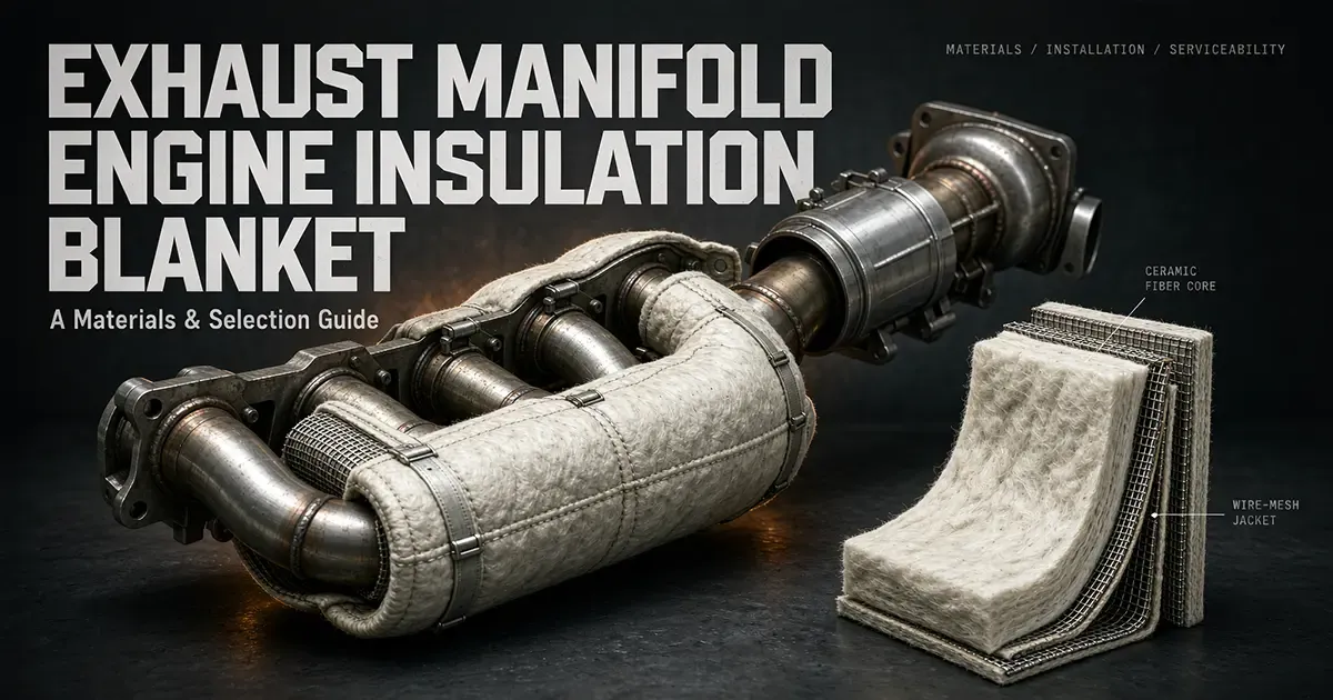
Exhaust-side soft insulation is not simply "wrapping up something hot". It is a coupled thermal, mechanical and corrosion design, constrained by four requirements: protected components must stay below their limits, hot components must not lose the cooling they were designed for, the assembly must not trap water, and the insulation must be restorable after maintenance. The priority order is fixed:
- Component protection - wiring harnesses, fuel and oil lines, hoses, connectors, sensors and structural parts near the hot surface.
- Compartment conditions - bulkhead and hood inner surfaces, touchable surfaces, engine bay air temperature.
- Personnel burn protection and fire risk.
- Exhaust energy, boost response or fuel savings - these are side effects, never the design driver.
Marine rules make the safety logic concrete: surfaces above 220 °C that could be reached by a fuel or lubricating oil system failure must be properly insulated, insulation that is oil-absorbent or oil-permeable must be encased in steel sheathing or equivalent, and removable sections must be provided for maintenance. That is a compliance floor, not a statement that every outer surface must sit below 220 °C.
A caution that most aftermarket content omits: some engine manufacturers' own application guides explicitly do not recommend soft blankets over exhaust manifolds, turbochargers and other engine components, because unapproved shielding can raise component skin temperatures and shorten manifold life. A dry manifold is designed to reject heat outward and deliver exhaust energy to the turbine. The OEM preference is therefore an approved rigid air-gap shield, a double-wall housing or a water-cooled design; aftermarket blankets belong only inside a boundary that has been approved by the engine or turbocharger maker, checked with a thermal model or bench test, and designed to drain and to be inspected. The popular claim that a turbo blanket "lowers intake temperature" does not hold as a general rule: it reduces local radiant heat flux, but if it simultaneously raises the air temperature near the compressor inlet or blocks cooling airflow outside the cover, the net effect can go the other way.
1. Name the Part Correctly: Four Solution Types
"Blanket" is used loosely for four different products. A technical specification should name part, construction and performance together - for example "turbocharger housing removable composite jacket, hot-face limit T_h, outer surface acceptance T_c, N cycles" - rather than "one turbo blanket".
| Term | Typical construction | Primary function | Boundary |
|---|---|---|---|
| Insulation blanket | Fiber core, stitched or bound outer fabric, metal mesh or foil, springs or ties | Conforms to manifolds, turbine housings and bends; cuts local radiation | Only on approved or verified hot faces; "wrapping it" is not a cooling design |
| Wrap / tape | Narrow fiber tape spirally wound, often coated | Pipe runs, tight-radius bends, local repair | Forms continuous wet seams, hard to inspect, large hot-face variance; use with care near flanges and sensors |
| Rigid shield | Stamped or welded double-wall metal, heat shields, air gap, occasionally a small core | Blocks radiation, stops splash, provides structure and an airflow path | First choice where space allows; needs expansion, vibration isolation, edge thermal bridges and condensate control |
| Removable jacket | Custom-cut panels, abrasion-resistant outer fabric or foil, buckles, spring clips or straps, often with a drain point | Flanges, turbines, turbochargers, valves and aftertreatment front sections that are serviced often | Best for marine, off-highway and generator service; higher cost, dependent on accurate contours and batch consistency |
2. The Four Temperature Layers
Exhaust gas temperature, metal hot-face temperature, insulation cold-face temperature and compartment air temperature are four different variables. Gas temperature follows load, air-fuel ratio, injection or ignition timing, EGR rate, aftertreatment state and altitude. Wall temperature also depends on local convection, radiation, coolant and oil galleries and thermal inertia. Blanket outer temperature depends on core conductivity, compressed thickness, external convection and whether a dead air pocket has formed.
| Layer | Engineering definition | Design anchor | Duty to record |
|---|---|---|---|
| T1 - gas side | Internal manifold surface, local metal peak near turbine inlet | A material classification temperature cannot substitute for it | Rated and maximum torque, towing or grade climbing, transient acceleration, hot soak after shutdown |
| T2 - hot face | Temperature of the manifold, turbine housing, flange or pipe that touches the blanket inside | Sets metal fatigue, sealing, coating and core limits | Final 30 minutes of steady state, peak after shutdown (heat soak-back) |
| T3 - cold face | Outer fabric, mesh or shield surface | Sets adjacent-part limits, touch safety and compartment temperature | Rated continuous, worst-case cooling airflow, hot soak |
| T4 - ambient | Local compartment air, bulkhead inner surface, intake air mass | Sets heat accumulation and ventilation demand | Airspeed or vessel speed and load spectrum, dead zones inside enclosures |
Three common figures deserve correction. "Manifold and exhaust pipe at 800-950 °C" describes a local gas or hot-face candidate range on some high-load gasoline direct-injection or performance engines - it is not a universal value; a purchase condition should read "engine model, measurement point, duty cycle, duration", for example "150 mm upstream of the turbine inlet, 30-minute mean and 1-second peak at a defined test cycle". "600-800 °C" better describes mid-section exhaust pipe, turbine housing skin or a cold-face candidate range than a universal blanket working band, and must be corrected with infrared imaging plus embedded thermocouples, because emissivity, reflective metal and dust skew infrared readings badly. "Turbine housing above 1000 °C briefly" can occur, but it cannot be treated as a long-term license for a finished blanket that also sees vibration, contamination, compression, stitching and outer-layer degradation. If a supplier claims "1000 °C contact", ask whether that is continuous or peak, for how long, in what atmosphere, at what cold-face temperature, at what compression ratio, with or without airflow, and which revision of the test report they mean.
3. Temperature Banding and Design Margin
The bands below are internal engineering controls, not regulations.
| Band | Long-term or repeated hot face | Typical location and strategy | Starting material or construction |
|---|---|---|---|
| A | ≤450 °C | Rear pipe sections, engine bay shields, cold side of lines inside acoustic enclosures | Qualified glass fiber or mineral wool composite, or low-temperature aerogel; outer layer still governs |
| B | 450-750 °C | Mid and rear exhaust pipe, some turbine outlets, after measurement | High-silica or quartz fabric composite, good refractory ceramic fiber or mid-temperature aerogel; halide control and drainage |
| C | 750-1000 °C | Rear manifold sections, turbine housing, front bends under high steady load | Approved high-purity or zirconia-bearing ceramic fiber system, double layer or air gap, metal outer sheath; bench validation required |
| D | Above 1000 °C or high-frequency transients | Turbine inlet hot spots, racing and special transients, local hot zones on gas engines | Do not rely on a "1430 blanket" label; prefer OEM thermal management, air gaps or metal screens, and validate material plus structure together |
Design margin should follow degradation paths rather than a flat minus-100-degree rule. If the supplier's declared continuous limit is T_cont, the prototype peak hot face should satisfy T_h,peak ≤ T_cont minus a design margin built from four contributions: batch scatter, performance loss after contamination or oil soaking, vibration wear allowance, and unknown transient allowance. Where testing is insufficient, a nominal margin of not less than 100 °C on soft blankets is a defensible starting point, and any hot face above 1000 °C should be treated as requiring special approval. Aerogel follows the same logic: products are classified at 200, 450 and 650 °C plus a manufacturer-declared class above 650 °C, and long-term service temperature is generally 50-150 °C below the classification temperature, so a 650 °C class does not automatically permit 650 °C against a hot face.
4. Materials: A Grade Is Not a Finished-Product Rating
4.1 Ceramic fiber blanket
Needled aluminosilicate blanket is built from alumina-silica fibers needled into a three-dimensional network. Published product ranges run roughly 64-160 kg/m³, with common cut parts near 96, 128 and 160 kg/m³. Higher density usually improves compression resistance, vibration resistance and initial insulation, but adds weight, heat capacity and cost; lower density conforms more easily but thins under spring pressure and dusts in airflow. Standard thicknesses start at 6, 10, 12, 19 and 25 mm, but thickness is not a performance promise: a nominal 19 mm blanket compressed 30 percent, cinched under wire mesh, on the inside of a bend or at a flange edge has a completely different real thickness.
"1260" and "1430" are classification temperatures, assigned by the permanent linear change on heating - the grading logic tests that shrinkage stays within a specified limit, typically 4 percent for soft products such as blanket, felt and paper and 2 percent for rigid products, with grades marked in 50 °C steps. A 1260 grade therefore means the material met that threshold under defined test conditions. It does not mean 1260 °C continuous service, and it certainly does not mean that stitching, wire, coating, adhesive, outer fabric or contaminants also survive 1260 °C.
Common chemical families have these engineering starting bands: standard grades roughly 1000 °C long-term, high-purity around 1100 °C, high-alumina around 1200 °C and zirconia-bearing near 1350 °C. These are product-family experience bands only - formulation, grain growth, shrinkage and atmosphere differ by plant and batch, so the batch data sheet and aging report govern. A quotation that states only "1430 °C resistant" should be rejected.
The needled structure keeps the blanket lofty and extensible when it is uncompressed and not under tension; it does not make the fiber immune to dusting on a vibrating pipe. The outer layers carry a different job:
- Stainless wire mesh or expanded metal constrains fiber migration, resists impact and provides a load path for ties. Thin wire can wear through the blanket or abrade adjacent parts at high-frequency vibration and tight bends, and cut ends must be bound.
- Glass fiber or coated fabric improves abrasion resistance, erosion resistance and appearance. An ordinary glass fabric is never a 650 °C finished-product rating - resin or sizing can carbonize far below the fiber limit.
- Silicone, vermiculite and foil coatings can improve abrasion, reflectivity, oil and water resistance or particle erosion, but each layer has its own temperature, permeability and aging limits. Marine oil-absorbent cores must be enclosed in steel or equivalent sheathing; a coating is not a substitute.
- High-silica and quartz fabrics suit high-temperature outer or reflective layers thanks to their silica stability, but embrittlement, flex life, halide and alkali contamination and stitching material remain weak points. A supplier's "1000 °C long-term" claim for a specific fabric applies only to that product and requires a full construction report.
4.2 Rock wool, glass fiber and basalt
Rock and mineral wool is low cost, non-combustible and acoustically effective, but it is hydrophilic, compacts easily, carries a higher risk of salt and halide impurities, and generates difficult dust when cut. It fits remote pipe sections, rigid shield backing or low-temperature zones on marine and generator installations, but it should not be selected for a manifold or turbine purely because it is rated to 650 °C in a location with thermal cycling, vibration and possible salt spray. Corrosion under insulation is recognized as a distinct damage mode: carbon and low-alloy steel show localized corrosion and flaking scale, 300-series stainless steel can pit, and older chloride-bearing silicate insulation can drive chloride stress corrosion cracking.
Glass fiber is flexible, electrically insulating and easy to sew, which suits mid- and low-temperature shielding, cold faces of air gaps or rigid shield liners. Standard E-glass long-term service sits well below front-section exhaust hot faces, and strength loss, devitrification and outer resin limits at temperature must be listed separately. When a supplier says "glass fiber jacket to 650 °C", ask which layer they mean: the fabric, the stitching, the coating or the whole assembly's cold face?
Basalt fiber is reported in review literature at roughly a 650 °C ceiling with stability dropping noticeably between 400 and 500 °C. That figure comes from materials review literature, not from an engine blanket standard, so basalt is a mid-temperature outer fabric or pipe wrap candidate and should not skip full thermal-cycle validation on the strength of being a mineral fiber. Check alkali and salt spray resistance, sizing and weaving lubricants as well.
4.3 Silica, aerogel and composites
High-silica and quartz fibers fit composite structures that must be thin, flexible and hot on the outside; their value is in the fabric and reflective layers, not as a thick core. Aerogel composite blanket uses nanoporous structure to suppress gas convection and conduction and often achieves a given insulation target in less thickness and weight, but "aerogel equals 1000 °C contact" is just as wrong. Aerogel products are classified at 200, 450 and 650 °C plus manufacturer-declared classes above 650 °C, with long-term service generally 50-150 °C below classification. High-temperature aerogel composites can also dust, shed, creep under compression, suffer membrane damage and vary between expensive batches, so request vibration mass loss, compression recovery, water uptake and hot-face aging data.
The right approach to a composite is division of labor, not stacking brand names. A near-net-shape ceramic fiber or zirconia-bearing core takes the temperature and thermal shock; a thin air gap or low-emissivity foil interrupts radiation; an abrasion-, oil- and salt-resistant outer fabric or steel mesh takes the environment; mechanical fasteners move load off the fiber into metal. If the outer fabric fails first, the exposed core starts dusting; if the core shrinks first, the cover goes slack and forms a thermal bridge and flutter path. Service life is set by the weakest layer. Our ceramic fiber insulation hub covers the core materials and finished forms in more depth.
5. Four Solutions Compared
| Solution | What it solves | Biggest risk | Preferred use | Verdict |
|---|---|---|---|---|
| Removable composite jacket | Local heat reduction, service access, repeatable spare parts | Contour and batch variation, fastener fatigue, cost | Marine, off-highway, generator sets, turbo rebuild shops | First choice where maintenance is frequent, with both hot-face and cold-face acceptance |
| Rigid air-gap shield | Burn and fire protection, oil containment, controllable cooling, strength | Space, thermal expansion, vibration transmission, condensate | OEM, mining, machinery space fire protection, aftertreatment front sections | First choice for safety-critical locations |
| Soft blanket, bonded | Irregular hot faces, local radiation reduction, low weight | Raises component skin temperature, hard to inspect, wear-through and moisture | Only in approved or verified zones | Not a general aftermarket shortcut |
| Wrap / tape | Small-bore pipe, local repair, bend reinforcement | Spiral seam thermal bridges, trapped liquid, destructive removal | Auxiliary reinforcement only | Avoid permanently wrapping whole manifolds or turbines |
| Dimension | Removable jacket | Rigid shield | Soft blanket | Wrap |
|---|---|---|---|---|
| Hot-face capability | Set by core plus outer sheath; C and D bands need validation | Air gap lowers cold face; metal must take the heat itself | Conforms closely but resistance depends on compression | Multiple layers add resistance but store heat and hold water |
| Cold face and compartment control | Good when the outer skin is abrasion resistant and drained | Best; cooling passages can be designed | Moderate; edges and fasteners become hot spots | Uneven; spiral seams show striped hot spots |
| Thermal cycling and vibration | Depends on fasteners and preload; can be designed loose-coupled | Good, with expansion joints and flexible hangers | Good initially, compacts and wears through over time | Loosens or cuts grooves at high-frequency bends |
| Assembly | Needs accurate 3D data or patterns; first-article effort is high | Significant bracket, tolerance and expansion design | Field-cuttable, but casual cutting is a risk | Fastest, hardest to audit |
| Serviceability | Best; local opening | Fair; bolts and clips | Poor; often crushed or oil-bonded | Worst; usually cut off and rewrapped |
| Life predictability | Can be high with batch consistency and periodic inspection | High; metal fatigue is inspectable | Low to moderate; internal condition hard to sample | Low; invisible once water and grit enter |
| CUI and moisture | Controllable with drip edges, drains and removability | Controllable by avoiding closed water pockets | High risk: capillary core, faces that never dry | High risk: seams wick, condensation after shutdown |
| Fire and oil resistance | Steel outer sheath is the best route | Good | Poor without a sheath; oil soaking amplifies hazard | Poor without a sheath |
| Procurement consistency | Needs contour ID, revision, BOM and aging reports | Needs drawings, certificates and weld or surface specs | Hardest to control: same roll, different batch | Same, with the largest workmanship factor |
| Cost | High first article, potentially low life-cycle | High tooling, low maintenance | Low material, high hidden failure cost | Lowest material, high rework cost |
6. Designing a Removable Jacket
A good removable jacket is a tailored garment, not gauze bundled around a pipe. The inputs are not "diameter times length" but 3D scan or pattern data, flange and sensor coordinates, hot-face measurement points, motion envelope, tool access path, adjacent-part temperature limits, cooling airflow direction, and the sources of condensate, salt spray and oil mist. Turbo rebuild shops in particular should maintain a jacket revision for each turbine model, actuator and oil or coolant connection - never force an old jacket for a similar housing.
A sound build-up assigns explicit roles from hot face to cold face:
- Hot-face layer. Select a ceramic fiber, zirconia-bearing or verified high-temperature composite core, and write fiber orientation, density and compression ratio into the process. Adhesive, ordinary polyester thread and nylon fasteners must never be exposed on the hot side; high-temperature thread, wire or ceramic rope needs a material certificate and a temperature curve.
- Compression layer or air gap. Add high-temperature padding or a local low-density transition under flanges, clamps and spring clips so a point metal load cannot compress 19 mm into 8 mm. Where needed, use a two-stage structure: hot-face half shell, air gap, cold-face cover.
- Abrasion-resistant outer fabric. It carries friction, oil mist and air erosion. Choose a tested coating, high-silica or glass composite system, and never substitute "the cloth does not burn" for "the assembly is rated". Fold and lock-stitch edges; no loose fiber ends may face a touchable surface or fan airflow.
- Metal mesh, foil or thin sheet. Mesh constrains fiber; continuous foil or thin sheet provides oil, salt and reflective protection. If aluminum foil is used, confirm its softening limit and its mechanical fixing - a reflective foil is not a structural layer. Marine oil-absorbent cores should be enclosed in steel or equivalent sheathing per IMO MSC/Circ.647 guidance.
- Edges and openings. Use split covers or small removable doors at flanges, oxygen sensors, exhaust gas temperature probes, turbo actuators and oil return lines, with continuous binding at every opening; raw core edges must not be left exposed. Allow for thermal expansion in the design direction - for bending sections and long straights this should be established by measurement after prototype thermal cycling, and a first article can start with roughly 1-2 percent geometric allowance along the free length as an initial window. Too much compressive strain buckles and wears; too little tears.
- Fastening system. Springs maintain variable preload as the assembly expands, stainless buckles or cam locks allow service access, ties suit low-shear areas and metal clips suit high-vibration points. Never use thin wire as the only long-term tie - it cuts at edges. Every fastener should be captive, anti-scuff and loss-protected, and positioned away from thermal imaging blind spots.
- Drainage rather than absolute sealing. Marine, off-highway and water-cooled or wet-area equipment should have drip edges or drain holes at low points, with seams facing upstream or uphill to avoid horizontal water pockets. Fully sealing an assembly does not make it dry: shutdown condensation, salt spray and minor leaks still collect at the cold end. Drains must not route hot or rusty water onto harnesses, connectors or rotating parts.
- Identification and spares. Mark part number, hot-face orientation, batch, installation date, applicable serial numbers and a no-unauthorized-modification notice, and supply a diagram with torque and fastener list. Deliverables should include a first-article report, material batches, a dimensional pattern, and post-cycle thickness and cold-face temperature. Refurbished and new jackets belong under separate revision control.
7. Installation: Lap, Fixing, Clearance and Drainage
Lap width, fastener spacing and clearances must all be derived from heat path and mechanical load. A 50 mm lap is a reasonable engineering starting minimum for flat, non-eroded sections with bound edges and a non-oil-absorbing core; on the inside of bends, at flanges, at vertical drip edges, at vibration nodes, around turbo actuators or where the outer sheath is continuously lapped steel, it should be widened to a value verified on the prototype. No general engine blanket standard mandates 50 mm, so it should never be quoted as a regulation.
| Item | Suggested starting window | Condition and acceptance |
|---|---|---|
| Longitudinal and circumferential lap on split jackets | 50 mm or more on the first article; widen in high-risk zones after verification | Widen where bends, drip edges or thermal imaging show seam hot spots; do not let the lap become the only heat path |
| Field seams on soft blanket | Staggered and bound; 50 mm or more on straights as a lower bound | Seams must not land on flanges, sensors, minimum curvature or maximum vibration nodes |
| Fastener or band spacing | 100-200 mm for initial trial layout, then fixed by vibration and compression uniformity | Not a regulatory value; densify at edges, abrupt span changes and the lower end of vertical runs; never cinch through the blanket |
| Clearance to harnesses and hoses | Do not rely on a fixed clearance; satisfy the adjacent part's temperature rating plus the measured cold-face temperature | Where no approved shield exists, one vehicle packaging guidance used about 127 mm from the heat source - a single case reference, not to be extrapolated |
| Clearance to combustible or heat-sensitive parts | Require both the part's certified temperature and a checked touch-temperature rise | Marine rules impose mandatory insulation above 220 °C; many vehicle standards require effective shielding of combustible material within 100 mm of the exhaust, subject to the applicable scope |
A practical installation sequence: clean and confirm the substrate has no cracks or leaks; restore original heat shields and supports; dry-fit and mark hot and cold faces; cut, bind and stagger seams; pre-assemble and simulate thermal expansion and tool access; preload lightly in a diagonal or alternating pattern; check for voids, exposed cut edges and pipe stress; agree a hot re-torque strategy; run steady-state and hot-soak thermal imaging; then inspect compression, wear marks and metal contact after cooling.
Fixings must distinguish hot side from cold side. On the hot side, no ordinary plastic tie, nylon fastener, rubber sleeve, halogen-bearing tape or unrated silicone; prefer metal springs or stainless fasteners and move point loads off the fiber through a high-temperature pad. On the cold side, plastic parts, webbing and labels are acceptable only within their own temperature curves. Vibration protection is less about adding more ties than about eliminating slap: the blanket must not float on the pipe, the cover must not hard-contact an adjacent bracket, and edges must not periodically rub an oil line or harness. Any component near rotating parts, turbine wheels, actuator linkages or exhaust flex sections needs full-travel and six-direction vibration checks.
The most dangerous illusion after installation is "the outer surface is not hot, so it worked". A compliant cold face with an over-limit hot face - caused by excessive thickness, blocked airflow or local compaction - is exactly the soft-blanket failure mechanism. Acceptance therefore needs hot-face measurement points, or an approved calculated correlation, together with cold-face thermal imaging. Keep logging for 30-60 minutes after shutdown to capture the soak-back peak; bearing housing and seal ring soak on gasoline and high-output engines matters, but that is internal turbocharger thermal management and cannot be solved by an external blanket alone.
8. The Steel Corrosion Debate: Water, Halides and Crevices
"Wrap makes steel rust" is half true and half oversimplified. Carbon steel in dry, continuously hot service is not especially prone to active corrosion; the risk concentrates in start-stop, low-load, coastal or washdown, rain and snow, and shutdown condensation cycles. Absorbent fiber, capillary laps, horizontal water pockets and damaged outer sheathing hold water against the steel while oxygen and electrolyte keep arriving, and localized corrosion follows. Corrosion under insulation as a damage mode covers localized corrosion under the covering, scale, pitting, and chloride stress corrosion cracking of austenitic stainless steel. The causal chain should therefore read: a covering structure that traps water and salt in a crevice, plus metal in a susceptible temperature and humidity window, plus stress or a broken passive film, produces CUI or external stress corrosion cracking. It is not that the fiber is chemically aggressive to steel.
Stainless steel does not "refuse to rust" either. Marine salt spray, cleaning agents, seawater splash, chloride-bearing binders and fillers and aged silicate impurities can wick with water onto 300-series surfaces; as the water evaporates the halides concentrate, and with thermal and assembly stress this can progress to pitting, crevice corrosion or external stress corrosion cracking. Standardized test methods for insulation against external stress corrosion cracking of austenitic stainless steel cover mineral wool, calcium silicate, composite silicate, perlite, foam glass, aerogel and binders, and note that in the absence of inhibiting ions such as silicate and sodium, chlorides and fluorides can cause cracking. Procurement therefore cannot stop at "is the chloride in ppm zero" - it must also ask about leaching and wicking, installation contamination, site salt spray and waste-water paths.
Design measures that work:
- Prefer a non-hygroscopic or verified hydrophobic system on the hot end; never place a bare mineral wool core directly against a wet-area marine or off-highway component.
- Keep the outer sheath continuous, oil-resistant and salt-spray resistant, with seams following water flow and drip edges at low points; IMO MSC/Circ.647 requires steel or equivalent sheathing where insulation may absorb or transmit oil.
- Never stuff blanket edges into flange faces, under clamps or into thread relief grooves to form a capillary seam; use formed grommets at openings.
- Isolate stainless fasteners from carbon and halogen-bearing contamination; clean dust thoroughly after cutting or grinding and never rinse with chloride-bearing cleaners.
- Avoid hammock-style water pockets on horizontal pipe; drain at low points and provide anti-siphon breaks or removable drip covers on vertical runs.
- After shutdown in humid conditions, keep machinery space ventilation and dehumidification consistent with operating procedure - "another layer" is not moisture control.
- For carbon steel manifolds and brackets, substrate coating and the covering are two separate defense lines: the covering can be inspected and removed, while the coating must remain effective within the supplier-approved temperature range after thermal cycling.
Post-removal inspection should happen after cooling, tagging and photographing. Look first for water marks, salt bloom, scale, pits, freckling on stainless, seized fasteners and discoloration at crevices; then apply visual plus thickness or ultrasonic checks by risk, sampling critical load-bearing parts under the plant integrity program. Loose scale should not simply be brushed off and re-covered - establish first whether wall thickness, cracking or thermal fatigue exceed component limits. Cores that are oil-soaked, salt-loaded or dusting should be scrapped, not flipped and reused. Reinstallation must replace damaged sheathing and fasteners, restore the drainage direction and be recorded in the maintenance order; engine manufacturer guidance also requires confirming that insulation has been correctly reinstated after repair, and marine guidance lists post-maintenance reinstatement as a routine check.
9. Safety, Health and Compliance
Insulation failure is itself a safety risk; fiber dust is a separate occupational health risk. During installation, burns come from the hot face and flying debris; in service, failures appear as hot spots, oil-soaked smoldering or fire, chafed harnesses and detached covers; during removal, dry fiber and binder release respirable particles. Controls must cover five layers - isolating the heat source, local exhaust or wet suppression, PPE, cleaning and waste - not merely a pair of gloves.
The health assessment of ceramic and vitreous fibers cannot be reduced to the word "asbestos". Refractory ceramic fiber is classified by the international cancer research framework as a man-made vitreous fiber with inhalation toxicology concerns, with limited evidence of carcinogenicity in humans, which places it in Group 2B. The engineering response is control rather than panic: eliminate dry cutting, blow-down and shaking; where wetting is impossible use local negative-pressure extraction; wear respirators suited to the dust task, long-sleeved clothing against fiber penetration, gloves and eye protection; keep contaminated workwear out of living areas; use HEPA vacuuming or wet wiping and never compressed air. Specific respirator classes and occupational exposure limits must follow the jurisdiction, current regulation, safety data sheet and site monitoring - no single national milligram limit should be presented as a global number.
Compliance runs on at least three parallel tracks:
- Product and fire performance - verify non-combustibility, smoke toxicity and customer specifications for the target market. "Non-combustible" does not mean it cannot burn skin, cannot conduct heat, or remains safe after oil soaking.
- Marine fire protection - the IMO logic behind MSC/Circ.647 is binding: surfaces above 220 °C that could be reached by a fuel or lubricating oil failure must be properly insulated, insulation must include removable sections for maintenance, oil-absorbent or oil-permeable layers must have steel outer sheathing, and reinstatement must be confirmed after maintenance. Class societies, flag states and machinery space categories may be stricter.
- Vehicle, off-highway and power generation - check the applicable vehicle, engine, acoustic enclosure, plant room and hazardous-area rules. Published automotive practice requires that no combustible material sits within 100 mm of the exhaust system unless effectively shielded, and that compartment insulation must not readily absorb fuel or lubricating oil without an impermeable covering.
Never remove a jacket while the engine is running, hot, or near a fuel leak. Hot surfaces plus oil mist are the classic machinery space fire chain, and marine risk material repeatedly lists inconsistent insulation quality, vessel age, failed reinstatement after repair and oil-soaked insulation as recurring concerns. Performance marketing claims must never override these safety preconditions.
10. Segment-by-Segment Application Logic
Passenger cars and performance aftermarket. Space is tight, plastic and electronics are everywhere and airflow is complex. Prefer OEM-approved local rigid shields, double-wall metal covers and short composite jackets; fully wrapping a manifold belongs only on specific engine-maker-approved parts. Acceptance focuses on ignition coil and injector harness, fuel rail and connector cold-face temperatures, firewall heat flux, idle-in-traffic soak, full-load grade climbing and 60 minutes after shutdown. Do not use "intake temperature dropped a few degrees" as the only KPI: a turbo blanket may reduce radiant heat into the bay while retaining heat on the exhaust side and raising local air temperature near the compressor inlet; the net effect requires simultaneous measurement of boost pressure, exhaust gas temperature, compressor inlet distribution and coolant or oil temperature. Vendor case figures describing a specific hot face, cold face and duty cycle cannot be converted into a purchase commitment.
Trucks, buses and commercial vehicles. Long high-load operation and repeated braking or downhill cycles make the aftertreatment front section, turbine outlet, heat shielding and the frame, harness and fuel line corridor the priorities. Removable jackets suit turbines and flanges because diagnostic access, sensors and pipework are serviced often; permanent wrap fights annual inspection. Watch exhaust flex sections, brackets and frame torsion - a cover must not become a second load path. On the side facing combustible interior or luggage compartments, apply the applicable vehicle shielding rules rather than treating a cool outer fabric as proof of bulkhead heat flux compliance.
Marine engines. Priorities are fuel and oil ignition control, salt-spray CUI and service access. Surfaces above 220 °C that could be reached by an oil system failure are the mandatory starting point. Prefer rigid double-wall screens or removable steel-sheathed jackets, never expose an oil-absorbent core, and design drip edges, drains and quick release for roll, spray, washdown and condensate. Silencers, flexible exhaust hangers and separation from fuel tanks and lines must also satisfy the applicable class society and flag requirements. Salt spray testing must simulate drainage paths, fastener crevices and post-service reassembly, not just spray the outer cover. Our marine engine room insulation guide covers the SOLAS A-60 side of this in more detail.
Off-highway and mining. Explosion protection, hot-surface limits and extreme dust are common. Some mining scenarios require engine surfaces below 200 °C, but that is a site condition under specific mining, explosion-protection or class requirements, not a universal limit for every excavator or loader. Choose impact-resistant rigid screens first and add removable composite jackets only in approved locations; pre-cleaners, hydraulic lines, harnesses and battery compartments are thermal imaging priorities. Dust blocks the venting path of outer sheathing and abrades fabric edges, so maintenance intervals should be shorter than for road vehicles. Equipment washed with high-pressure water must be able to open and dry the jacket - do not seal water inside the blanket.
Generator sets and stationary power. Containerized units run continuously with limited natural or forced ventilation in acoustic enclosures, and the classic failure is "local insulation succeeds, enclosure heat balance degrades". Establish the unit heat balance first: intake louvres, radiator recirculation, exhaust air short-circuiting, control cabinets and battery rooms all belong in the model. Removable jackets suit turbines, flanges and service valves; remote large pipe can use rigid sections. Acceptance uses rated-load steady state plus the permitted overload or derating spectrum plus shutdown soak, and records ambient temperature, altitude and intake-to-exhaust air temperature difference. Any claimed reduction must state hot face, cold face, distance from the cover, airspeed, load and initial condition, otherwise the numbers are not comparable. Marine generator sets add the MSC/Circ.647 fire and removable-maintenance requirements on top.
11. Selection Decision Flow
- Are there mandatory surface temperature, fire, explosion-protection or class requirements? If yes, lock the applicable standard revision and test body before discussing materials. If no, adjacent-part temperature limits and fire risk remain the floor.
- Which hot-face band applies - A up to 450, B 450-750, C 750-1000, D above 1000 °C or high-frequency transients? For D, prefer OEM thermal management or rigid air gaps and treat soft blankets as special approval. For C, use a high-purity or zirconia-bearing ceramic fiber system with metal sheathing and bench validation. For B, weigh high-silica or quartz composite, aerogel or ceramic fiber against cost and thickness. For A, glass fiber or mineral wool composite can be economic but still needs oil and water protection.
- Is there moisture, salt spray, oil mist, washdown, vessel roll or shutdown condensation? If yes, no bare hydrophilic core: steel sheathing, drip edges, drainage and CUI inspection enter the bill of materials. If no, condensation and cleaning agents still apply - never claim permanent dryness.
- Is maintenance frequent, are sensors dense, is this a turbo rebuild environment? If yes, removable jackets with revision control and a recorded baseline for service hours. If no, evaluate a rigid shield to reduce soft seam count.
- Is there vibration, a flex section, bracket load transfer or edge chafe risk? If yes, loose-coupled fastening, anti-chafe pads, expansion allowance and post-vibration re-torque. If no, still complete full-duty thermal cycling and road or sea trials.
- Prototype with dual temperature measurement, thermal imaging and teardown. If it passes, freeze the revision; if it fails, change the structure rather than only adding thickness.
A purchase specification should state, at minimum, hot-face mean and peak with duration, cycle count, atmosphere and cold-face limit; fiber chemistry, density, thickness, thread, mesh, adhesive and coating grades with batch; thermal resistance at a stated compression ratio with measurement points and method; aging data covering thermal cycling, compression creep, vibration mass loss, dusting and shrinkage; salt spray, oil immersion, washdown and fire or smoke results under the applicable standard; fastener material, preload method, expansion allowance and edge binding; first article, batch certificate, dimensional pattern and change notification; and dual hot-face and cold-face acceptance with imaging, teardown and reinstatement tolerance.
12. Glossary
| Term | Definition in this guide |
|---|---|
| Hot-face temperature T_h | Highest metal or gas-side temperature the insulation touches or faces; measurement point and duty must be defined |
| Cold-face temperature T_c | Outer or sheathed surface temperature; not the same as compartment air temperature |
| Classification temperature | Grade point set by a standardized permanent linear change test, not a finished-product continuous rating |
| Continuous service temperature | Temperature at which a specific construction, atmosphere, load and life target allows repeated operation, as defined and verified by the supplier |
| CUI | Corrosion under insulation, driven by water, electrolyte, crevice and thermal cycling together |
| ESCC | External stress corrosion cracking of austenitic stainless steel under concentrated halides, moisture and stress |
| Heat soak-back | After shutdown, when cooling flow stops and residual exhaust-side heat flows back into the turbocharger bearing housing and seals |
| Thermal bridge | Metal fasteners, compression marks or exposed edges that sharply lower local thermal resistance |
Material forms, temperature classes and typical applications for the fiber cores are covered in ceramic fiber blanket temperature grades, the ceramic fiber blanket product page and the rock wool insulation hub. For thin, space-constrained builds see aerogel insulation; for jacket construction similar to kiln and oven doors, see oven and kiln door insulation; and for how material choice interacts with budget, see the industrial insulation material cost comparison 2026.
Frequently asked
Does a turbo blanket really lower intake air temperature? +
It may reduce radiant heat into the engine bay, but that does not automatically lower the actual compressor inlet temperature. The net result depends on hot-face location, airflow outside the cover, heat pickup in the intake duct, radiator recirculation and load. Compare multi-point compressor inlet temperature, exhaust gas temperature, boost pressure and bay thermal images against a baseline - a vendor's single-point reduction is not a universal promise.
Can an insulation blanket overheat or damage the turbocharger? +
Qualified external insulation is not itself a heat source, but if it blocks the cooling the manifold or turbine housing was designed for, skin temperature and post-shutdown soak-back can exceed component limits and accelerate thermal fatigue, seal and lubrication problems. Some engine makers explicitly do not recommend unapproved blankets on manifolds and turbochargers. Verify the hot face, not just the outer fabric.
How thick should an exhaust insulation blanket be? +
There is no lookup table. Start from the allowable cold-face heat flux or temperature, the hot-face peak, the material's compressed conductivity, external convection and available space; 6-25 mm is simply the common process window. Excessive thickness crowds airflow, compacts, raises local fastener temperature and obstructs servicing. Accept with prototype thermal resistance and measured compressed thickness.
Does exhaust wrap make steel pipe rust? +
The fiber is not chemically attacking the steel. Wrap creates capillary paths, crevices and water pockets that keep water and salt against the metal, and start-stop wet-dry cycles trigger corrosion under insulation. Carbon steel corrodes locally; 300-series stainless can pit or suffer external stress corrosion cracking. Use sheathable, drainable, removable construction and inspect periodically.
How long does a removable insulation jacket last? +
No universal number of years applies. Life is set by hot-face peak and cycling, vibration, oil, salt and water exposure, outer fabric wear, fastener preload and the number of removal cycles. Request cold-face, thickness, dusting and tensile data after thermal cycling and vibration aging, set inspection intervals from imaging and teardown, and scrap any jacket that is oil-soaked or crushed.
Should I choose a 1260 or 1430 grade ceramic fiber? +
Calculate the real hot face first, not the highest instantaneous exhaust reading. Candidate hot faces in the 750-1000 °C range may justify high-purity or zirconia-bearing systems with dedicated validation; above 1000 °C or under high-frequency transients, do not order on a 1430 label alone - prefer air gaps or rigid thermal management. Also confirm outer fabric, thread, mesh and adhesive limits, because the finished continuous rating equals the weakest layer.
Can DPF and EGR components be wrapped directly? +
Not as a general rule. Diesel particulate filters and catalysts have target temperature windows, thermal uniformity and control logic that blind insulation can disturb, changing regeneration behaviour and thermal stress; EGR pipes and valves also involve condensate corrosion, control accuracy and nearby plastic or rubber parts. Follow the aftertreatment supplier's permitted thermal boundary and control strategy, and avoid sensors, pressure lines and actuators.
Must the whole jacket come off for maintenance? +
The design goal should be local opening, not destructive removal. Make flanges, turbine, actuator, temperature and pressure sensors and oil connections into split flaps or small doors. If every service event requires cutting straps and crushing the core, the design is unsuitable for frequently serviced equipment. Reinstatement must restore drainage direction and fastener batch.
How should drainage and corrosion inspection be handled? +
Let seams and low points form controlled drip edges rather than horizontal water pockets, and route drains away from harnesses and connectors. Inspect periodically with the engine cold, looking for salt bloom, scale, freckling, wire cut marks and caked core material, and apply thickness checks on critical parts under the plant integrity program. Marine and salt-spray installations need shorter intervals than road vehicles.
Is a 50 mm lap mandatory for installation? +
No verified general engine blanket standard mandates 50 mm. It is a reasonable engineering starting point for flat, non-eroded sections with well-bound edges; widen it at bends, flanges, drip edges, high-vibration zones and material transitions based on thermal imaging and teardown. The real acceptance criteria are seams without hot spots, no exposed core, no wear-through and uniform compression - not a ritual number.
Request a quote
Interested in our insulation solutions? Send us your requirements and our team responds within one business day.