
Cryogenic Tank Insulation for LNG: Materials and Boil-Off Control
How cryogenic tank insulation works for LNG at -162 °C: three-zone onshore stacks, membrane and vacuum systems, material behavior, failure modes and a selection matrix.
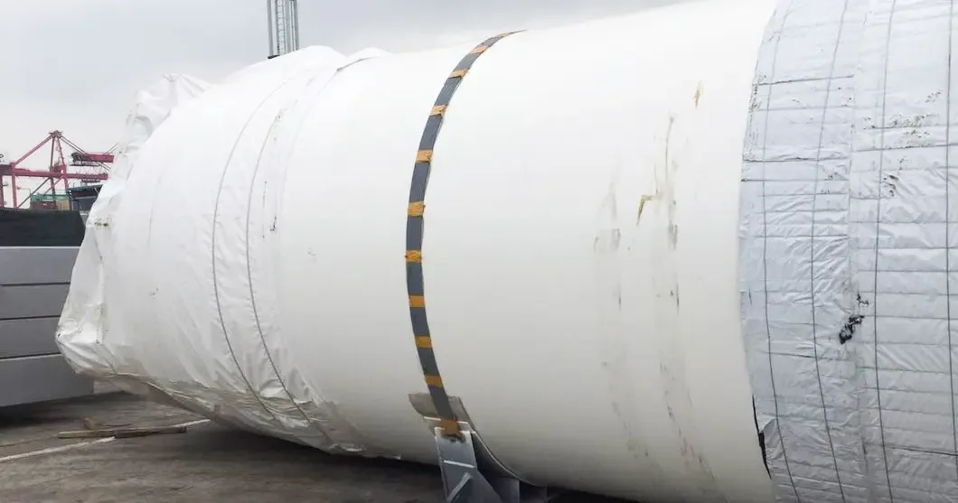
Liquefied natural gas is stored and shipped at approximately -162 °C, and every watt of heat that leaks through the tank envelope becomes boil-off gas. Cryogenic tank insulation is therefore never about eliminating heat transfer — no material can do that — but about controlling the rate at which heat enters, so evaporation stays within the allowances of the containment system and the economics of the project.
This guide covers insulation for LNG storage tanks and cryogenic vessels: onshore full-containment tanks, membrane and self-supporting marine tanks, road tankers, ISO containers and small vacuum vessels. Piping and cold-storage warehouses are separate engineering problems with their own treatments.
Why Cryogenic Tank Insulation Is a System Decision
Steady-state heat leak into a tank follows the familiar relation Q = U × A × ΔT, where the temperature difference between ambient and cargo approaches 180 K for LNG service. The boil-off rate is that heat leak divided by the latent heat of vaporization, normally reported as a percentage of tank volume per day.
Two consequences follow, and both matter in procurement:
- There is no universal thickness or single best material. A 200,000 m³ terminal tank and a 50 m³ road tanker hold the same fluid, but the small tank has far more surface area per unit of stored volume, so its percentage evaporation is structurally harder to control. Real designs are validated with a project-specific heat-and-mass model that includes supports, nozzles, pump columns and piping — paths that often exceed the one-dimensional wall loss.
- Conductivity alone does not rank systems. k-Value depends on mean temperature, gas pressure, density, aging and moisture. A value measured at 10 °C says almost nothing about behavior at a -165 °C mean temperature.
Onshore Full-Containment Tanks: A Three-Zone Insulation Stack
A modern onshore LNG storage tank is usually a full-containment design: an inner tank of 9% nickel steel inside a prestressed concrete outer tank. Each zone of the insulation system does a different structural job, which is why a single material is never specified for the whole tank.
| Zone | Dominant material | Why it is selected |
|---|---|---|
| Wall annulus | Expanded perlite, loose fill | Economical, noncombustible bulk fill that flows around internal steelwork |
| Base | Cellular glass brick, layered courses | Load-bearing, near-zero moisture uptake, dimensionally stable under the inner tank |
| Suspended deck / roof | Layered glass wool plus elastic felt | Conformable, noncombustible, tolerates thermal movement across multiple layers |
Field evidence supports this conventional stack. A published 220,000 m³ full-containment project used perlite in the annulus, five layers of cellular glass brick under the base, and fifteen layers of glass wool in the suspended deck, with resistance-temperature-detector and fiber-optic monitoring plus an online perlite top-up system to correct settlement. Perlite's known weaknesses — settlement, bridging, and performance loss when wet — are managed by design (top-up nozzles, fill-density control, vapor management) rather than by substituting a different material.
Marine, Road and Mobile Tanks: Membranes, Vacuum Annuli and Foam Cores
Membrane cargo systems on LNG carriers place reinforced foam panels between metallic primary and secondary membranes; prefabricated insulation boxes transfer cargo loads into the hull while insulating it. Reported boil-off guarantees for such systems have improved from roughly 0.15% of tank volume per day in earlier designs to 0.07–0.085%/day in current ones, through thicker panels, better joints and dual-barrier redundancy. That progress is a system outcome, not a single-material improvement. None of these figures are fleet averages: they are reported design outcomes, and installed performance depends on construction quality, joint tightness and commissioning discipline as much as on the panel specification itself.
Self-supporting independent tanks take a different route: metallic shells with external foam panels, and cellular glass layers where thermal mismatch between structure and insulation must be managed.
Road tankers and ISO tank containers are thickness-constrained mobile systems. Two families dominate: high-vacuum annuli with multilayer insulation (MLI) for long holding times, and simpler PUR/PIR foam cores where installed cost matters more than hold time. Published standard limits for static evaporation illustrate the volume effect: for high-vacuum multilayer LNG tank containers, allowed limits fall from about 0.30%/day at 100 m³ to 0.15%/day at 500 m³. Small dewars and stationary vacuum vessels go further still, combining MLI with adsorption getters.
Piping on any of these systems is its own design topic — see the dedicated cryogenic pipe insulation guide; cold-storage warehouses are covered in cryogenic insulation applications.
How Materials Actually Behave at -162 °C
Cryogenic service qualifies materials on properties that ambient datasheets never show:
- Thermal contraction. Differential contraction opens joints and detaches linings. Cryogenic-grade PIR panel specifications, for example, require a mean linear expansion coefficient no greater than 7.0 × 10⁻⁶ K⁻¹ together with a k-value no greater than 0.015 W/(m·K) at a -165 °C mean temperature. A building-grade PIR datasheet does not qualify a panel for cargo containment.
- Cold embrittlement. Materials that are flexible at room temperature may stiffen, crack or delaminate at -162 °C; binders, facings and reinforcements contract at different rates.
- Moisture as a system failure. Wet fibrous insulation raises conductivity sharply and can freeze into ice bridges. Closed-cell cellular glass is specified at tank bases precisely for its moisture stability under load.
| Material | Typical conductivity (state the condition) | Density / strength | Role in tank systems |
|---|---|---|---|
| Expanded perlite, atmospheric | Validated by project use, not a single k-number | Low bulk density; settles | Annular fill, onshore tanks |
| Cellular glass | ≈0.043–0.048 W/(m·K) at ~10 °C (ambient reference) | 120–160 kg/m³; 0.8–1.6 MPa compressive | Load-bearing bases |
| Cryogenic PIR panels | ≤0.015 W/(m·K) at -165 °C mean (qualified grades) | Grade-dependent | Membrane carrier walls |
| Silica aerogel blanket | ≈0.014–0.020 W/(m·K) (ambient claims; cryogenic data per product) | Low; fragile core | Valves, nozzles, retrofits |
| Glass wool / rock wool | ≈0.031–0.048 W/(m·K) at 25 °C (ambient) | Resilient; needs vapor management | Suspended decks, warm-side boundaries |
| MLI in high vacuum | System-level value only | Layer stack | Road tankers, dewars |
Silica aerogel blankets deserve one procurement note: hydrophobic treatment is often fluorine chemistry, so request a chemical declaration and fluorine-free alternatives for the exact grade and production site.
Where Nano Microporous Boards Earn Their Place
Rigid silica microporous boards reach roughly 0.020–0.024 W/(m·K) at moderate temperatures in a fraction of the thickness of fibrous products, and they tolerate warm-side service up to 1000 °C — useful where one material must bridge a mixed-temperature interface. In cryogenic tank work, the realistic roles for a nano insulation board are:
- Valve boxes, nozzles and penetration packings, where geometry defeats both slabs and blankets;
- Thickness-limited hybrid panels for LNG fuel systems and compact skids, combined with foam or vacuum layers;
- Cold-box and regasification internals, where thin rigid panels simplify support design.
They are not a replacement for perlite in a 200,000 m³ annulus or for structural cellular glass under a tank base — the volumes and loads are wrong for a board product. For a head-to-head comparison of the ultra-thin families, see our nano vs aerogel vs microporous analysis.
Standards, and How to Read a k-Value Claim
Facility and vessel codes frame the design: NFPA 59A and EN 1473 for onshore LNG installations, the IMO IGC Code for gas carriers, and ISO 21029 for cryogenic vessels within its size and pressure range. Product families sit underneath: ASTM C552 for cellular glass, ASTM C578 for polystyrene foams, and EN 14303 for mineral wool products.
For performance claims, ASTM C1774 governs thermal performance testing of cryogenic insulation systems. A credible datasheet states mean temperature, boundary temperatures, gas pressure or vacuum level, density and test method. If a supplier quotes one number at 10 °C and another at -165 °C, those values support different decisions and must never be plotted as a direct ranking.
Failure Modes That Drive Lifecycle Cost
Most cryogenic tank insulation failures are system failures rather than material defects:
- Perlite settlement and bridging distort heat flow. Online top-up and fill-density control are proven countermeasures.
- Wet insulation freezes, bridges and destroys the thermal case. Find the ingress source — roof membrane, seal, drain — instead of adding thickness.
- Thermal bridges at supports, pump columns and nozzles often exceed the theoretical wall loss. They need a three-dimensional model and thermal breaks, not more powder.
- Vacuum loss in MLI systems is invisible until evaporation drifts upward. Protected test ports and periodic integrity checks are essential.
- Corrosion under insulation on the warm side: keep outer surfaces above the dew point and specify low-chloride products wherever water can appear.
Boil-off economics make these failures expensive twice — lost cargo plus the energy to reliquefy or otherwise manage the gas. A total-cost comparison should use installed cost plus lifetime BOG value, never material price per cubic meter.
What to Ask a Supplier Before You Buy
Because cryogenic tank insulation is a system purchase, the request for quotation should ask for evidence, not just prices. A disciplined RFQ includes:
- Test conditions for every k-value: mean temperature, boundary temperatures, gas pressure or vacuum, density and method. Values quoted without conditions cannot be compared.
- Cryogenic qualification data: linear shrinkage or expansion, cold flex behavior, moisture absorption and permeability for the exact product grade.
- Fire and smoke documentation, and where organic foams are proposed, the system-level fire analysis rather than a material rating alone.
- Chemical declarations for binders, facings and hydrophobic treatments — including fluorine-free status where regulations require it.
- Project references at comparable scale, ideally with operating evaporation data rather than design guarantees.
- Delivery and installation scope: layer counts, jointing details, top-up or re-evacuation provisions, and monitoring points for commissioning.
Suppliers who answer these questions precisely are also the ones likeliest to hold tolerances during installation — and installation quality, joint tightness and vapor-seal integrity decide whether the datasheet performance ever reaches the tank.
Selection Matrix: Matching Material to Tank Duty
| Duty | Starting point | Do not assume |
|---|---|---|
| Onshore full-containment base | Cellular glass brick system | Lowest ambient k means lowest boil-off |
| Onshore wall annulus | Expanded perlite with top-up | Zero settlement without management |
| Suspended deck / roof | Layered glass wool blanket or rock wool | One material suits the whole tank |
| Membrane carrier wall | Licensed cryogenic foam panel system | Building-grade PIR is acceptable |
| Road tanker, long hold | Vacuum + MLI + getters | Blanket k predicts tank boil-off |
| Road tanker, lowest cost | PUR/PIR foam core | No hold-time penalty |
| Valves, nozzles, retrofit | Aerogel blanket or microporous board | One thickness fits all hardware |
| Small dewar / vacuum vessel | MLI with getters | All multilayer stacks perform alike |
For application-level guidance across LNG and cold-chain service, see our cryogenic insulation hub; the cryogenic insulation materials overview maps every product family to its temperature window and load role.
Frequently asked
What is the best insulation for an LNG storage tank? +
There is no single best material. Onshore full-containment tanks conventionally combine expanded perlite in the wall annulus, load-bearing cellular glass at the base and layered glass wool at the suspended deck. Membrane carriers use cryogenic-qualified foam panel systems, while mobile tanks choose between vacuum-multilayer and foam-core designs by hold time.
What temperature is LNG stored at in insulated tanks? +
LNG is stored at approximately -162 °C at near-atmospheric pressure. Insulation systems are qualified against cryogenic mean temperatures — cryogenic panel grades, for example, are specified at a -165 °C mean temperature — and the design must keep outer surfaces above the dew point to avoid condensation and corrosion.
How is boil-off gas rate calculated for an LNG tank? +
In steady state, heat leak Q = U × A × ΔT is divided by the latent heat of vaporization to give a mass rate, then normalized against tank volume as percent per day. Real designs use validated models that include supports, nozzles and piping, because these thermal bridges often exceed the one-dimensional wall loss.
Why is cellular glass used under LNG storage tanks? +
Base insulation carries the weight of the inner tank and its cargo. Cellular glass combines useful compressive strength (0.8–1.6 MPa across common grades), near-zero moisture uptake and dimensional stability at cryogenic temperature, which is why layered cellular glass brick remains the default under onshore tanks.
Can silica aerogel replace bulk insulation in LNG tanks? +
Not in large tank envelopes. Aerogel blankets are credible for piping, valves, nozzles and retrofit zones where thinness and conformability justify the premium. For annular fill and structural bases, perlite and cellular glass remain the proven systems. Ask suppliers for cryogenic test data and fluorine-free hydrophobicity declarations.
What standards apply to LNG tank insulation? +
Facility design follows NFPA 59A or EN 1473; ships fall under the IMO IGC Code; cryogenic vessels are covered by ISO 21029. Product standards include ASTM C552 for cellular glass and EN 14303 for mineral wool, while ASTM C1774 defines how cryogenic thermal performance should be tested and reported.
Request a quote
Interested in our insulation solutions? Send us your requirements and our team responds within one business day.