
Aircraft Thermal Insulation for Nacelles and Equipment Bays
Aircraft thermal and acoustic insulation for engine nacelles and equipment bays: how material families map to duty zones, why airworthiness rules differ by location, and a practical selection matrix.
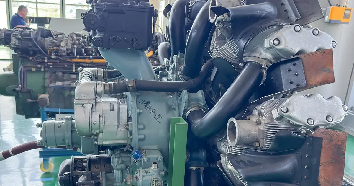
Industrial insulation felt and an airworthy installed insulation article are not the same object. Between the raw fiber and a flight-approved component sit several qualification jumps: facing, edge closure, stitching, fire sealing, metal or plastic fasteners, and a drawing with a part number. That gap is exactly why aviation insulation deserves its own engineering discipline rather than a "lower-k-value" shopping decision.
This guide covers civil aircraft — fuselage thermal-acoustic insulation, engine nacelles and pylons, environmental-control and bleed-air ducts, and auxiliary-power-unit bays. Space-launch and spacecraft insulation are a different problem set and are covered separately in our aerospace and defense thermal insulation overview.
Why Aircraft Insulation Lives in Its Own Rulebook
The most useful sentence in any aviation-material discussion is this: a material specification is not an installation approval. A technical standard for, say, fibrous glass blanket can define density, flammability, hydrophobicity, service temperature, apparent thermal conductivity, airflow resistance and tensile strength — yet still say nothing about whether a finished blanket satisfies fire, material-qualification, process-qualification and type-certification requirements for a given aircraft.
Three consequences follow:
- Approval attaches to the installed article and its approval basis, not to the bulk material. A parts-manufacturer approval covers a specific modified or replacement article for specific models under a stated approval basis; similarity to another approved item is never, by itself, enough.
- Military or test-rig heritage is evidence input, not a shortcut. Military-derived qualification data must be mapped clause-by-clause to civil rules; where civil requirements are not met, additional testing is required regardless of "similar hardware" arguments.
- The real certification object is a configuration, not a sample. Any change to formulation, facing, adhesive, density, thickness, edge closure or fastener reopens a material, process and configuration-change assessment.
The Regulatory Map: Cabin, Blankets, Powerplant and Fire Zones
Different locations on the aircraft answer to different rule domains, and conflating them is the most common early mistake.
- Occupied-cabin materials sit on the basic fire-safety threshold for cabin interiors; large panels, partitions, galley structures and large stowage structures add heat-release and smoke criteria. This is the floor, not the whole airplane.
- Thermal/acoustic insulation installed in the fuselage has its own flame-spread and flame-penetration rules; for larger passenger airplanes the lower half of the fuselage adds a penetration test because these materials often sit in inaccessible areas where a hidden fire could spread.
- Flammable-fluid zones are not solved by "non-combustible" alone. Leakage zones must be analyzed or tested to show ignition probability is reduced and consequences controlled, and absorbent material near flammable-fluid components must be covered or treated so it cannot soak up hazardous quantities of fluid.
- Fire resistance is judged on function-continuity plus no-flame-penetration plus no-cold-side-ignition, typically demonstrated in a 2000 °F (about 1093 °C) flame for a defined duration. A small Bunsen test on a coupon does not stand in for a full-assembly fire test; our notes on A1 non-combustible insulation systems walk through the classification logic that also informs aviation fire-zone material choices.
- Powerplant and APU bays are designated fire zones with their own design rules, separate from cabin and blanket clauses.
A European operational rule even folds thermal-acoustic insulation of in-service large airplanes into continuing airworthiness, so a material swap on an existing type is a modification-path question, not a spare-parts purchase.
Material Families and Where Each Belongs
Industrial datasheets are useful for screening, not for design values. The table below separates "typical industrial capability" from "candidate aviation finished article"; the installed boundary is always the validated finished part.
| Family | Typical continuous use | Where it fits in aviation | Key disqualification risks |
|---|---|---|---|
| Glass fiber (aviation grade) | up to about 370 °C per ASTM C800 | fuselage, low-temp ECS, nacelle cold side | fine-fiber control, airflow erosion, compression set, thermal-wet aging |
| Polyimide foam | roughly to 200 °C | fuselage, low-temp ECS, some APU periphery | sustained burn, hot-end ceiling, fluid compatibility, compression fatigue |
| Amorphous alumina-silicate fiber (ceramic fiber) | about 1000 °C with margin | core-cowl mid-hot zones, non-direct-impingement | devitrification above ~950–1000 °C, shedding, fine-fiber health |
| Polycrystalline alumina / mullite fiber | up to about 1400 °C by grade | higher hot-end, long-life hot zones | cost, brittleness, chipping, high-temperature conductivity |
| Silica-aerogel / fiber composite | about 200 °C standard; higher grades per spec | space-limited sandwich, ducts, local panels | brittle edge failure, creep, oil/moisture, cost |
| Mineral wool (industrial) | about 350–650 °C by grade | ground test rigs, non-installed thermal baselines | wet absorption, fiber release, not directly airworthy |
Our ceramic fiber board and glass wool blanket pages profile the fiber families most relevant to mid- and low-temperature aviation candidates, and our nano insulation board covers thin-function-layer options. Industrial rock wool board is a useful baseline for ground rigs but is not a drop-in airworthy nacelle material.
Nacelle Hot-Side Duty: Why Surface Temperature Drives Design
A nacelle design input must capture far more than "exhaust temperature." The real boundary set is: hot-side radiation and convection temperature, cold-side allowable temperature, hot-spot location, duration, thermal-cycle count, internal and external pressure, local airflow velocity, impacting-particle environment, adjacent-metal thermal-expansion mismatch and maintenance accessibility.
Published nacelle and pylon research places blankets on the inner side of the fan cowl, the inner side of the core cowl and the bottom area of the pylon, and recommends a combined route of analytical thermal modeling, coupon insulation testing and environmental qualification before re-measuring performance. That sequence matters because the published summaries do not by themselves prove a specific formulation or an installation approval.
Aerogel is a good cautionary example. Its room-temperature conductivity can be extraordinarily low, but at elevated temperature radiative transfer through the silica network can raise effective conductivity by an order of magnitude. High-temperature designs must use representative finished thickness and temperature, and usually add opacifiers — the supplier's 25 °C nameplate number multiplied by area is not a thermal design.
The practical nacelle rule is "multi-layer temperature matching," not one fiber blanket covering everything: light thermal-acoustic material on the fan and outer-cowl cold side, a ceramic-fiber core with temperature margin on the core cowl, polycrystalline alumina or ceramic composite at local hot spots and radiative peaks, a flow- and dust-blocking skin on the high-pressure fast-flow side, and a wear- and acoustic-friendly removable inner layer near moving parts, harnesses and access surfaces.
The Failure Starts at the Edges: Five Engineering Constraints
Insulation failure in service almost never begins in the middle of the pad. It begins at interfaces.
- Airflow erosion. High-speed hot gas turns the insulation into part of the internal flow field. Seam orientation versus the boundary layer governs fiber trailing and edge lift-off; holes, sharp edges and sagging invite flutter. Coupon-level mass loss, edge wear, stitch pull-out, facing cracking, thickness change and cold-side rise must all be measured in a representative flow path.
- Vibration and repeat removal. "Soft" becomes "permanently crushed" under clamp preload, temperature, oil contamination and a vibration spectrum. Compression rebound, compression set, post-fatigue thickness recovery and fastener wear must each be measured separately — not just a fresh-sample rebound at 25 % compression.
- Fluid absorption. Jet fuel, turbine oil, hydraulic fluid and de-icing fluid change burn behavior, conductivity, mass and maintenance risk. "Hydrophobic" means water-repellent, not oil-repellent; zones with oil mist need cleanable, replaceable outer skins as a design gate.
- Fiber migration. Amorphous alumina-silicate, polycrystalline and glass fibers can all form respirable or surface contaminants. Finished parts need full edge binding, stitched sealing, reinforced openings, low-shedding facings and anti-abrasion liners, with "no visible fiber migration, no foreign-object entry into oil, bleed-air, sensor or actuator systems" written into acceptance and inspection.
- Galvanic corrosion. Stainless outer skins touching aluminum, titanium or carbon-fiber structure, with moisture, salt fog and electrolyte in the interlayer, drive galvanic corrosion; heat can accelerate oxidation and halogen catalysis. Material data should state chloride, fluoride, soluble salts and pH extractables and compatibility with aluminum, titanium, stainless, nickel alloy and carbon-fiber composites, followed by humid-heat, salt-fog and thermal-cycle cross-section inspection.
A published airworthiness directive once required short-interval visual inspection and mandatory replacement of a specific APU exhaust insulation blanket — a reminder that hot-end nacelle and APU blankets are continuing-airworthiness-critical items, not fit-and-forget consumables.
A Layered Concept: Five Functional Zones, Not Two Pads
Rather than two sheets stuck together, a defensible concept separates functions from the environment side to the structure side:
- Outer protective facing — carries high-speed flow, erosion, fluid splash, part of the radiation and edge protection.
- Fire- and gas-blocking seal layer — stops flame and contaminant tracking along the interlayer.
- Primary insulating core — carries most of the temperature drop.
- Spacer / resilient layer — provides thermal-expansion give, vibration relief and contact-resistance control.
- Inner wear / acoustic layer — faces access surfaces, harnesses, actuators or local high-speed flow.
Fire zones add a barrier layer at the critical thermal path identified by analysis. The outer facing must not sacrifice breathability, drainage and maintainability: metal foil reflects radiation and blocks fluid but can buckle, fatigue and corrode and adds weight; coated fabric is lighter and formable but must prove temperature, abrasion, post-flame integrity and edge closure. Where condensation or oil mist exists, design a controlled vent or drain rather than a sealed, un-inspectable water pocket.
Airworthiness Path and a Practical Selection Matrix
Step one is defining the application boundary, not buying material. For a type-certificate holder, the blanket may belong to an engine-nacelle installation or to the airframe design; for a modified or replaced article on an already-certified aircraft, the path runs through type certificate, supplemental type certificate, parts-manufacturer approval or a continuing-airworthiness change, depending on installation impact and approval basis. A qualification database — material and process specifications, batch acceptance, statistical process control, environmental limits, long-term durability and key-process parameters — should be the project foundation, not a pile of papers assembled at certification close-out.
A four-gate pass-fail discipline beats a one-time "qualified" label: (1) material and regulatory suitability, (2) environmental durability, (3) component-level fire and function, (4) full-scale and flight. Any gate failure sends the item back to root cause rather than "retest until pass."
| Duty | Sensible starting point | Do not assume |
|---|---|---|
| Fuselage, low-temp ECS | glass fiber blanket, polyimide foam, flexible aerogel composite | lowest k-value wins |
| ECS hot sections >250–370 °C | validate point by point against pipe temperature and local radiation | one blanket fits all pipe runs |
| APU and exhaust isolation | powerplant fire-zone system, not a general blanket | "installed once, maintenance-free" |
| Nacelle core hot wall | ceramic-fiber core with margin, then polycrystalline at peaks | a single fiber blanket covers the whole nacelle |
| Space-limited ducts, local panels | aerogel composite sandwich with protected edges | thin blanket automatically beats thicker core |
| Any fire-zone interface | qualified firestop plus non-combustible insulation, re-reviewed per modification | a material rating covers the penetration |
For the space-grade systems that share some materials with these aviation candidates, see our aerospace propulsion thermal management and high-temperature sensor insulation notes; the qualification logic is related but the rule domains differ.
Frequently asked
What materials are used for aircraft thermal and acoustic insulation? +
Civil aircraft use aviation-grade glass fiber blankets for fuselage and low-temperature environmental-control sections (up to about 370 °C per ASTM C800), polyimide foam for light self-supporting acoustic duties, amorphous alumina-silicate (ceramic) fiber for core-cowl mid-hot zones near 1000 °C, polycrystalline alumina or mullite fiber for higher hot-end zones, and silica-aerogel composites for space-limited sandwich layers. Industrial mineral wool is a ground-rig baseline, not a directly airworthy nacelle material.
What regulations govern aircraft insulation materials? +
Cabin interiors answer to the basic fire-safety thresholds with added heat-release and smoke criteria for large structures; fuselage thermal-acoustic insulation has its own flame-spread and flame-penetration rules plus a penetration test for larger airplanes; flammable-fluid zones require analysis or testing of ignition probability and fluid absorption; fire zones are judged on function continuity, no flame penetration and no cold-side ignition in a 2000 °F flame; and powerplant or APU bays are designated fire zones under separate design rules.
Why can't industrial insulation be installed directly on an aircraft? +
A material specification defines properties of the bulk product, not the installed, flight-approved article. The airworthy object is the finished blanket with its facing, edge closure, stitching, fire seal and fasteners under a specific approval basis. Military or test-rig success is only evidence input and must be mapped clause-by-clause to civil rules; similarity to another approved item is never sufficient by itself.
How is nacelle insulation designed for the hot side? +
Design input is the hot-side radiation and convection temperature, cold-side allowable temperature, hot-spot location and duration, thermal-cycle count, pressure, local airflow velocity, particle environment and maintenance access — not the bare exhaust temperature. The usual approach is multi-layer temperature matching: light thermal-acoustic material cold side, ceramic-fiber core with margin, polycrystalline or ceramic composite at peaks, a flow-blocking skin, and a removable wear or acoustic inner layer.
What causes aircraft insulation to fail in service? +
Failures start at interfaces: airflow erosion and edge lift-off, vibration-driven permanent crush under clamp preload, fluid absorption that changes burn and conductivity behavior, fiber migration into oil, bleed-air, sensor or actuator systems, and galvanic corrosion where stainless skins meet aluminum, titanium or carbon-fiber structure with moisture and salt. Good designs close every edge, seal every opening and specify cleanable, replaceable outer skins.
How is aerogel used in aviation insulation? +
Silica-aerogel composites serve space-limited sandwich layers, ducts and local panels where thin high-insulation value offsets cost and fragility. Their effective conductivity rises sharply at temperature because of radiative transfer through the silica network, so high-temperature designs must use representative finished thickness and temperature and usually add opacifiers; the supplier's 25 °C nameplate number is not a thermal design value.
Request a quote
Interested in our insulation solutions? Send us your requirements and our team responds within one business day.