
Insulation R-Value Explained for Industrial Projects
R-value is thermal resistance, not a material grade. Learn how R relates to thermal conductivity, why pipe R is logarithmic, and how to specify resistance for industrial walls, roofs and pipes.
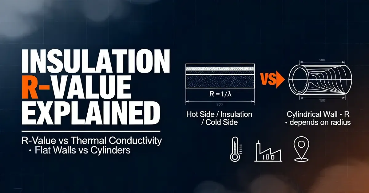
Insulation R-Value Explained for Industrial Projects: What the Number Means—and When It Doesn’t
Executive summary: R is a resistance, not a universal grade of insulation
Insulation R value is not a material “efficiency rating” you can compare in isolation. In its most useful engineering sense, R is the resistance offered by a defined body or assembly to steady one-dimensional heat flow: the temperature difference divided by heat flow. For a flat, homogeneous layer, R = d / λ, where thickness d is in metres and thermal conductivity λ is in W/(m·K); the SI result is m²·K/W, often called RSI. Double the thickness and conduction resistance doubles, if λ and the boundary conditions stay the same; halve λ and resistance doubles.
Three distinctions prevent the most expensive specification errors:
- Material resistance is not assembly resistance. A pipe or wall also has surface films, contact resistance, air spaces, liners, cladding and, in real buildings, thermal bridges.
- R is not the whole heat-transfer problem. Convection at surfaces, radiation across cavities, air leakage and solar gains can dominate even when the insulation’s laboratory R is excellent.
- A plane-layer R cannot be pasted onto a pipe. Cylindrical layers have increasing area with radius, so resistance is logarithmic:
R′ = (1 / 2πλ) ln(r₂/r₁)per metre of pipe, notd / λ.
For procurement, the practical rule is simple: specify the performance objective, the service conditions and the calculation method—not just “R-something.” A cold-water line needs a dew-point check; a steam header needs an economic-thickness and personnel-protection check; a roof needs a code and whole-assembly U-value check. Industrial insulation is therefore rarely solved by copying a residential wall R-value.
This article is a technical explainer, not a project-specific compliance opinion. Final values must be checked against the jurisdiction’s adopted code, the facility’s operating envelope, the material manufacturer’s declared or design values, and the full mechanical design.
1. The vocabulary: R, λ, U and “apparent R” answer different questions
The fastest way to read an R-value is as a thermal bottleneck. Given a steady temperature difference ΔT across a defined path, a larger R means a smaller heat flow. That makes R invaluable for comparing alternative constructions, but only when the comparison holds the geometry, mean temperature, moisture state and boundary conditions steady.
| Quantity | Symbol | Definition | SI unit | Engineering question |
|---|---|---|---|---|
| Thermal conductivity | λ | Conductive heat flux per unit area per unit normal temperature gradient | W/(m·K) | How readily the material itself conducts? |
| Material-layer thermal resistance | R_layer | d / λ for a uniform flat layer | m²·K/W (RSI) | How much resistance does this layer add? |
| Assembly/element total thermal resistance | R_tot or R_0 | Sum of layer, surface and relevant linear/path resistances for the defined path | m²·K/W | How much does the whole element resist heat flow? |
| Thermal transmittance | U (or K) | 1 / R_tot for an area-normalised element | W/(m²·K) | How much heat moves through the whole element per °C and m²? |
| Cylinder resistance per length | R′ | Temperature difference divided by heat loss per unit pipe length | m·K/W | How much does one metre of insulated pipe resist heat flow? |
The ISO-aligned calculation framework treats building components as combinations of homogeneous layers, including air layers; it is not a model of every industrial fitting, support, valve or multi-dimensional joint. The Chinese national-method record confirms that the current ISO 6946 line is a calculation method for building components and elements made of homogeneous layers (including air layers). That scope is useful for a panel or flat roof, but a pipe, vessel, flange and support constellation needs the cylindrical extension and engineering judgment.
1.1 The flat-layer equation is deliberately simple
For a single uniform layer with heat flow normal to the surface:
R_layer = d / λ

where
d  = thickness, m
λ  = thermal conductivity, W/(m·K)
R_layer = thermal resistance, m²·K/W
Heat flow per unit area is q = ΔT / R_layer under the one-dimensional, steady-conduction ideal. For n layers in series with good contact:
R_layers = d₁/λ₁ + d₂/λ₂ + … + dₙ/λₙ
A practical assembly total used in building envelopes also includes interior and exterior surface resistances, R_i and R_e, so R_0 = R_i + Σ(d_j/λ_j) + R_e and U = 1/R_0. Those surface films are boundary conditions, not magic properties of the foam. Wind, orientation, emissivity, surface temperature and whether a cavity is ventilated can move them.
Key takeaway: “R-10 board” is ambiguous until you know the unit system, declared thickness, mean temperature, moisture condition and whether the number includes facers, air films or only the core.
1.2 r-value vs thermal conductivity: one is intensive, the other is extensive
Thermal conductivity is a material property; R is a property of a body. λ belongs to the material (modulated by temperature, moisture, density, ageing and, in some porous or semi-transparent products, radiation through the pores). R belongs to “this much of that material, in this geometry, under these conditions.”
| Statement | Correct interpretation |
|---|---|
| “Lower λ is better for insulation.” | Yes, all else equal: lower conductive transport per unit thickness. |
| “Higher R is better.” | Yes for the defined path and temperature difference, but it is not automatically lower installed cost, safer touch temperature or better condensation control. |
| “This product has a fixed R per inch.” | Only an approximation. It assumes a linear, geometry-independent relation and a declared λ over the stated condition. |
| “R and λ are interchangeable.” | No. R = d/λ and λ = d/R; thickness is the bridge. |
The term apparent thermal conductivity matters here. ASTM terminology warns that when non-conductive modes—radiation across pores, convection in a cavity, thickness effects or surface emittance—contribute, an “apparent” value may vary with specimen thickness and must be quoted for the test conditions. Research on foams likewise finds that effective conductivity changes with ageing and environmental parameters such as temperature and moisture, rather than remaining the single constant printed on a datasheet.
2. Units: an R-10 in Atlanta is not an RSI 10 in Antwerp
The number alone is dangerous. The United States commonly expresses thermal resistance as h·ft²·°F/Btu (often written R-10, R-30, etc.), while Europe and most technical work use RSI in m²·K/W. Both describe the same physics, but their scale differs by a factor of about 5.68.
Start from the exact relation for the reciprocal U quantities:
1 Btu/(h·ft²·°F) = 5.67826 W/(m²·K)
Invert it for resistance:
1 US R = 0.176110 ≈ 0.1761 RSI
1 RSI   = 5.67826  ≈ 5.678 US R
| You have… | Multiply by… | To get… | Example |
|---|---|---|---|
| US R (h·ft²·°F/Btu) | 0.1761 | RSI (m²·K/W) | R-13 → 2.29 RSI |
| RSI (m²·K/W) | 5.678 | US R | 2.29 RSI → R-13.0 |
| λ in Btu·in/(h·ft²·°F) | 0.1442 | W/(m·K) | A material comparison must convert before using d/λ in SI |
| λ in W/(m·K) | 6.9335 | Btu·in/(h·ft²·°F) | Same material, opposite unit direction |
Round to 0.176 and 5.68 only when a specification, label or internal template demands two-decimal convenience. Keep 0.1761/5.678 for calculations, and preserve the source value where a contract audit matters. Never call a 2.3 RSI product “R-2.3” in a US bid, or describe a US R-30 board as “30 RSI.”
Procurement checkpoint: Put the unit system in the title block of every datasheet, BOQ, drawing and energy model. “R-30” without a unit system is a change-order waiting to happen.
3. Planar walls and roofs: add layer resistances, then deal with the real world
For a flat, continuous layer, thermal resistances add like electrical resistors in series. This is why a specification can rationally say “add 50 mm of material X to an existing wall” and predict the conduction contribution. It is also why continuity matters more than a hero product: a thin, high-conductance path can short-circuit a thick, high-R blanket.
3.1 The calculation sequence that survives a review
- Define the thermal path. Interior air to exterior air? Process fluid to ambient? Entire assembly or just the insulation core?
- Collect design values, not catalogue best cases. Mean temperature, service life, humidity/exposure, compression, facing and test method.
- Compute each layer:
R_j = d_j / λ_j. For a declared product resistance, confirm thickness and unit basis before reuse. - Add the relevant series terms. Flat layer stack first; then surface resistances or convection/radiation terms if you are calculating an assembly U-value.
- Stop calling the result U until the area basis is complete.
U = 1/R_0only after films, framing/bridges or other area-normalised paths are consistently included.
| Flat assembly model | Equation | What it includes |
|---|---|---|
| Core only | R_core = Σ(d_j / λ_j) |
Insulation and substrate conduction contribution |
| Whole opaque element (ideal 1-D) | R_0 = R_i + Σ(d_j / λ_j) + R_e |
Interior and exterior surface boundary layers |
| Area-normalised heat flow | q = ΔT / R_0; U = 1 / R_0 |
Heat transfer per unit area |
| Real wall with repeating bridges | Area-weighted or numerical model | Studs, rails, concrete beams, penetrations, junctions |
EN ISO 6946-style methods are for homogeneous layers and building elements; a structure with significant two- or three-dimensional heat flow needs a more detailed method or validated software. The Chinese adoption of ISO 6946:2017 makes this scope explicit. In practice, continuous exterior insulation, staggered joints, thermal breaks at brackets, and attention to the junction of roof–wall–soffit are not “extras” to the R-value—they determine whether the calculated R survives installation.
3.2 Why a high-R core can still underperform
A layer’s R covers the conductive portion of transport through that layer. It does not, by itself, promise any of the following:
- no interior surface condensation;
- no solar heat gain through a glazed or metal-skin assembly;
- no air leakage through the insulation plane;
- no thermal bridging at steel, concrete or fasteners;
- no radiation exchange across an open or semi-open cavity;
- no loss of performance after wetting, compression or ageing.
Enclosed air spaces are a useful reminder. Their effective resistance depends on gap thickness, orientation, mean temperature, temperature difference and surface emissivity; they are not a material with a universal d/λ. ASHRAE Handbook-derived research on enclosed air spaces explicitly models the combined radiation and convection contribution rather than treating air as a simple solid slab.
4. Cylindrical pipes and vessels: the logarithmic rule changes the answer
A pipe is not a wall rolled into a circle. On a cylinder, the inner insulation surface is smaller than the outer surface. The same radial heat flow passes through an expanding area, so resistance grows logarithmically with the radius ratio—not linearly with thickness.
For a single homogeneous cylindrical layer of length L, inner radius r₁, outer radius r₂, with one-dimensional steady conduction and constant λ:
Φ = 2π λ L (T₁ - T₂) / ln(r₂/r₁)

Resistance of the layer:
R_layer = ln(r₂/r₁) / (2π λ L)      unit: K/W

Resistance per unit length:
R′ = ln(r₂/r₁) / (2π λ)              unit: m·K/W
Heat loss per metre is q′ = ΔT / R′. University heat-transfer material derives the same result for the multi-layer cylinder:
q′ = (T₁ - Tₙ₊₁) / Σ [ ln(rᵢ₊₁/rᵢ) / (2π λᵢ) ]
Each layer’s logarithmic term adds in series; you may not substitute (rᵢ₊₁ - rᵢ)/λᵢ for the annular geometry.
4.1 Two “equivalent R” numbers, two different jobs
| Basis | Formula | Unit | Reference area or length | Use it for | Do not use it as |
|---|---|---|---|---|---|
| Linear/unit-length resistance | R′ = ln(r₂/r₁)/(2πλ) |
m·K/W | 1 m of pipe | Heat loss per metre, economic thickness, steam/process pipe energy model | an “R-value” to compare directly with a flat wall board |
| Outer-area-equivalent areal resistance | R″_o = (r₂ - r₁)/λ = d/λ |
m²·K/W | Outer cylindrical surface area A_o = 2πr₂L |
Comparing the insulation as if it were a flat layer referenced to its outer surface | the actual cylinder heat flow, unless corrected with the logarithmic factor |
| Inner-area-equivalent areal resistance | R″_i = (r₂/r₁ - 1)·ln(r₂/r₁)/(2πλ) × 2πr₁… more simply, R″_i = R′ / r₁ when expressed as (K·m²/W per unit inner length?) |
m²·K/W referenced to inner area | Inner pipe surface | Reports that deliberately normalise to process-side area | a universal panel R-number |
The second basis is the source of most “but my pipe insulation says R-4 per inch” confusion. If a vendor quotes an areal R for a curved product, ask: is it referenced to inner area, mean area, outer area, or is it simply the flat-sheet d/λ? Only the last is geometry-independent—and only the logarithmic expression gives the correct cylinder heat flow.
For a thin annulus, ln(r₂/r₁) ≈ (r₂ - r₁)/r_m, so the cylinder result approaches the flat-plate formula using a mean radius. That is a useful sanity check, not a licence to use d/λ on a large-diameter vessel or thick insulation layer.
4.2 Multi-layer cylinder example you can audit
A pipe has three annular layers: pipe wall, inner insulation, outer insulation. The conductive resistance per metre is:
R′_cond = ln(r₂/r₁)/(2π λ_pipe)
        + ln(r₃/r₂)/(2π λ_inner)
        + ln(r₄/r₃)/(2π λ_outer)
Then add, in the proper physical sequence, the internal film/convection term 1/(2πr₁h_i), the external convection/radiation term 1/(2πr₄h_o), cladding and any contact gaps. The total lineal heat loss is:
q′ = (T_fluid - T_amb) / R′_total
A real industrial model also checks interface temperatures. The outer-layer material must be rated for the temperature at its inner face; a low-λ inner layer can make that interface hotter than a naive “bulk mean” estimate. This is one reason a two-material build needs interface-temperature verification, not just a summed marketing R.
Design sequence: This article establishes the thermal-resistance basis. To turn an allowable heat loss, surface temperature, dew point or payback target into a thickness, use the cylindrical equations above in the systematic workflow in how to calculate insulation thickness. That companion piece solves for thickness; this one explains what the resistance actually means.
5. Industrial selection: the right R is the one that satisfies the governing constraint
Industrial insulation is normally constraint-led, not “minimum R-led.” A building envelope may be checked against a prescriptive table; a process plant first asks what failure mode costs money or creates risk. Energy loss, process temperature, condensation, freeze protection, personnel protection, footprint, corrosion-under-insulation (CUI) risk, fire/smoke requirements and maintainability can push the answer in different directions.
The following bands are engineering starting points, not universal code requirements or product warranties. No single authority governs every steam, cryogenic, HVAC and chemical-process application worldwide, and the governing constraint can change by company standard, country, facility hazard area and client specification.
| Typical duty | First design driver | Practical starting R′/R thinking | What can override a bigger R |
|---|---|---|---|
| Chilled water / low-temperature cooling | Dew-point control, then cooling energy | Start from surface-temperature/dew-point margin; verify with ambient humidity and solar load | Space, vapor-retarder continuity, vibration, accessibility |
| Domestic/hot-water and HVAC distribution | Standby loss, delivery temperature, condensation | Compare energy loss per length with surface/dew-point constraint | Retrofit space, existing supports, damage and replacement frequency |
| Medium-temperature process fluids | Temperature stability, pumping/viscosity, energy | Economic thickness using operating hours, fuel price, heat lost | Process upset temperature, batch vs continuous duty, control valve noise/maintenance |
| Steam, heat-transfer fluid, high-temp equipment | Energy, surface temperature, material limits | Logarithmic cylinder model plus interface temperature | Personnel exposure, fire rating, CUI, expansion, removable covers on valves |
| Cryogenic / cold process | Heat ingress, freeze/spill protection, vapor barrier | Often high resistance, but must model multi-layer and moisture ingress | Embrittlement, permeability, venting, thickness/weight, cold bridge at supports |
A Chinese national industrial-insulation design source (GB 50264-2013) illustrates the multi-criterion logic: its published announcement identifies a mix of mandatory provisions, while the engineering record for that standard family separates energy-loss/economic thickness, allowable surface temperature, freeze/condensation and other duties. It is not US or EU law and should not be cited as such; its value here is the reminder that these are separate calculations.
5.1 Material families are levers, not automatic winners
| Family | Where it often earns its place | What procurement must verify |
|---|---|---|
| Mineral wool / fibrous blanket or board | High-temperature tolerance, fire behavior, permeability and easy shaping for plantwork | Temperature rating, compression, oil/water exposure, density, sag, cladding and CUI strategy |
| PIR / PUR foam | Good space efficiency in many moderate-temperature envelopes and some process duties | Closed-cell continuity, temperature range, fire/smoke toxicity, ageing, facing and joint sealing |
| Elastomeric/closed-cell foam | Tight-radius chilled-water and HVAC work, built-in vapour-retarder behavior in some systems | Service-temperature limits, adhesive/tape compatibility, UV/ozone exposure, seam workmanship |
| Aerogel blanket/composite | Space-constrained hot or cold assets, complex shapes, where thin build has operational value | Declared λ at service mean temp, compression, dust/handling, cost per unit R, jacket system |
The point is not to rank these materials by a single “best R.” A thin aerogel build can be excellent where real estate and complex geometry justify it; a thicker mineral wool system can be the rational choice where temperature, fire and cost dominate. For a direct material-level comparison without turning laboratory claims into universal rules, see aerogel vs polyurethane foam insulation.
6. United States vs Europe: same physics, different compliance languages
The biggest transatlantic risk is not the arithmetic; it is the document you think you are complying with. The US market commonly speaks in US R-values, ASHRAE methods and model-code adoption. European work more often uses RSI, declares performance under EN/ISO calculation routes, and then applies national building regulations that sit on top. Neither market lets you infer a legal requirement from the bare word “R.”
6.1 US framework: model standards, adopted by jurisdiction
ASHRAE 90.1 is titled around energy-efficient design of buildings other than low-rise residential buildings. Its envelope provisions are conditioned by climate zone, conditioning category and construction class, and it supports both prescriptive and performance paths. A publicly available reproduction of the 2019 SI edition shows the familiar structure: building envelope, HVAC, service water heating, power, lighting and appendices, including rated-R and assembly U-/C-/F-factor determination material.
The IECC is a separate model code family. Its residential and commercial provisions should not be treated as one table: occupancy, adoption date, state/local amendments and whether a project follows the residential or commercial path all matter. A US procurement specification that says only “meet IECC” is incomplete until it names the edition, jurisdiction, residential/commercial path and component assembly.
DOE climate resources support mapping and analysis but are not themselves the installer’s permit. Climate zone is an input to the applicable table or energy model, not a global instruction to “use more R.” A hot, humid location may need a different envelope strategy emphasizing shading, glazing solar control, moisture management and continuity as much as a thicker insulation blanket.
6.2 European framework: calculation method plus national implementation
EN ISO 6946 (Building components and building elements — Thermal resistance and thermal transmittance — Calculation method) provides the calculation grammar for homogeneous layers and building elements. The ISO 6946:2017 adoption record confirms the scope and the method-classification alignment. EN ISO 10456 addresses design values for building products and hygrothermal performance; its role is to move a declared laboratory property toward a value usable in design.
There is no single “European R-value” that overrides national energy codes, planning rules, member-state implementations or product CE/declared-performance regimes. The same RSI number can sit inside very different national U-limit tables, window SHGC rules, airtightness requirements and evidence formats.
| Question | US project habit | European project habit | Correct engineering response |
|---|---|---|---|
| Unit on drawing | US R (h·ft²·°F/Btu) | RSI (m²·K/W) | Convert once, lock units in the title block |
| Product property | ASTM-tested/declared R or λ, with grade and condition | EN/ISO declared and design values, with relevant product standard | Demand test method, mean temp, moisture/ageing basis |
| Assembly check | Assembly U/factor path in adopted model code/standard | EN ISO 6946 route plus national regulation | Do not transplant a US prescriptive table to Europe, or vice versa |
| Climate input | ASHRAE/IECC/DOE zone and local amendment | Climate region plus national implementation and moisture/wind context | Climate zone is an input, never the whole specification |
| Industrial pipe | Same logarithmic physics, project/company spec governs | Same logarithmic physics, project/company spec governs | Do not use a building-wall R table as the pipe requirement |
7. Climate zones: higher heating-R is a trend, not a blanket instruction
Colder locations generally reward more envelope thermal resistance, but the optimum component depends on the assembly. As heating degree days rise, the marginal saving from another increment of roof, wall or glazing improvement changes; so does the penalty of a thermal bridge. Yet a cold climate does not justify ignoring solar gain, indoor humidity, air leakage or summer overheating. Conversely, a hot-arid site can need massive envelope thermal inertia and radiant-control strategy, while a hot-humid site is often dominated by shading, ventilation/dehumidification and exterior-surface wetting risk.
The table below is intentionally a decision map, not a compliance table. Exact prescriptive R- or U-values move with every code edition, component type (roof above deck, attic, metal-framed wall, mass wall, fenestration), climate subzone and local amendment. The author could not verify a complete, license-free snapshot of the latest US and European numerical tables across all components as of this writing; claiming one would be worse than useless.
| Climate tendency | Envelope priority | Insulation implication | Industrial analogue |
|---|---|---|---|
| Heating-dominated / cold | Reduce transmitted loss; control bridges and infiltration | Higher assembly R and continuous insulation often valuable; check U and junction details | Hot-fluid lines: energy and freeze protection if idle; cold lines: larger dew-point margin |
| Hot, humid | Control solar gain, moisture and air leakage | Exterior-side continuity and vapour-aware detailing can matter more than raw R alone | Chilled water: vapour retarder, seam and support continuity are often the real job |
| Hot, arid | Limit radiant gain; consider thermal mass | High R helps, but surface reflectance/shading and dynamics also matter | Outdoor cold lines: solar gain can reverse the direction of heat flow |
| Mild / mixed | Balance seasonal loads and peak comfort | Optimise whole-year energy, not just winter R | Batch process or seasonal operation may favour different thickness than a 24/7 line |
ASHRAE 90.1’s framework conditions envelope choices on climate and conditioning category rather than offering a universal “wall R.” EN ISO 6946 supplies the component calculation, while the national rule supplies the target. For engineers, this separation is helpful: calculate in physics-first terms, then prove compliance in the jurisdiction’s language.
8. The seven mistakes that turn a good R-value into a bad project
| Myth | Why it fails | What to do instead |
|---|---|---|
| “Higher R always means thicker.” | R = d/λ. Lower λ can deliver more resistance in less space. |
Compare thickness, declared λ/mean temperature, cost and service limits together. |
| “R and λ are just two ways of saying the same thing.” | λ is material-intensive; R includes geometry and condition. | State both, plus thickness and unit system. |
| “R covers all heat transfer.” | It models a conduction path; convection, radiation, infiltration and solar gain sit outside the bare layer term. | Build a heat-balance model for the real assembly or pipe. |
| “A flat-wall R can be used on a pipe.” | Cylinder area expands with radius; the annular term is logarithmic. | Use ln(r₂/r₁)/(2πλ) per length and state the reference area. |
| “The datasheet λ is valid for the next 20 years.” | Ageing, temperature, moisture and compaction change effective performance. | Use a design value for the service class, with inspection and replacement planning. |
| “Wetting only changes weight.” | Water replaces low-conductivity pore air and adds transport mechanisms. | Require a vapour/moisture strategy, drainage/venting where appropriate, and a dry-state check. |
| “A radiant barrier is just high-R insulation.” | It primarily manages radiant exchange in an air space; its performance depends on emissivity, contact and geometry. | Model it as a radiation boundary condition, not as a solid-layer R. |
The moisture point is not theoretical. Experimental work on temperature and moisture effects found both variables can influence measured conductivity; for some materials, a simplified single-variable description is insufficient. For semi-transparent low-density materials, thermal radiation within the material can also complicate what a single “conductivity” reading means. This is exactly why purchasing on an unqualified “R per inch” can backfire after installation.
9. A procurement and engineering decision table you can actually use
| Decision gate | Minimum question | Evidence to request | Red flag |
|---|---|---|---|
| Unit integrity | US R or RSI? | Unit stated on every line item and drawing | “R-20” with no system |
| Material basis | At what mean temperature and condition? | Declared/design λ, test standard, ageing/moisture basis | A single λ over -200 °C to 600 °C |
| Geometry | Flat, curved, vessel, or complex fitting? | Calculation showing linear vs areal R basis | Pipe quoted with flat d/λ only |
| Assembly | Are films, cladding, bridges and air gaps included? | U-value or total-R model, not just core R | “R-30 wall” ignores steel and joints |
| Process duty | Energy, dew point, surface temp, or freeze control? | Governing constraint and operating hours | One thickness for every line in the plant |
| Environment | Wet, outdoor, UV, chemical, cyclic, CUI risk? | Temperature rating, absorption/desorption, jacket and seal details | Interior-lab performance used outdoors |
| Fire/safety | What does the hazard analysis require? | Reaction-to-fire, spread/smoke where applicable, plus surface-temp check | Thermal preference used to bypass safety spec |
| Installation | Who owns continuity? | Joint stagger, compression limits, supports, removable covers | Pallet R accepted as installed R |
10. Worked checks: the arithmetic behind confident specifications
10.1 Flat-layer sanity check
A 100 mm homogeneous layer has λ = 0.040 W/(m·K).
R_layer = 0.100 / 0.040 = 2.50 m²·K/W (RSI 2.50)
US R    = 2.50 / 0.1761 = R-14.2
If the same layer is compressed to 80 mm but λ is unchanged, resistance falls to 2.00 RSI (US R-11.4). If a lower-λ product at 0.028 W/(m·K) is used at 80 mm, resistance is 2.86 RSI (US R-16.2). Thinner can beat thicker when λ is better—but only for the tested, installed, dry condition.
10.2 Pipe sanity check
A 168.3 mm OD pipe (radius r₁ = 84.15 mm) has a 60 mm insulation annulus, so r₂ = 144.15 mm. Take λ = 0.045 W/(m·K).
r₂/r₁ = 144.15 / 84.15 = 1.713
ln(r₂/r₁) = 0.538

R′ = 0.538 / (2π × 0.045) = 1.90 m·K/W per metre
Heat loss per metre for a 150 K temperature difference would be 150 / 1.90 = 79 W/m from the insulation conduction term alone—before interior and exterior film resistances. The naive flat approximation d/λ = 0.060/0.045 = 1.33 RSI is not interchangeable with 1.90 m·K/W; it is a different quantity with different units and a different reference area.
If a second layer is added, extend radii and add another ln(r₃/r₂)/(2πλ₂). If the outer surface must stay below a touch-temperature limit, solve for the outer-surface temperature using the full series, including external convection and radiation—not by inspecting core R alone.
12. Conclusion: buy the verified performance, not the isolated number
The phrase insulation R value is useful only when it is a complete sentence: resistance of what, in which geometry, at what service condition, expressed in which unit system, and evaluated against which objective. The SI relation R = d/λ makes thickness and conductivity visible; the cylindrical relation R′ = ln(r₂/r₁)/(2πλ) protects pipe calculations from a flat-plate error; and the assembly relation U = 1/R_0 reminds the designer that films, bridges and real joints decide the delivered result.
For buildings, let the local adopted ASHRAE/IECC or European national framework set the compliance target, while EN ISO 6946 and ISO 7345-style definitions keep the arithmetic honest. For industrial assets, let the governing requirement—energy economy, process temperature, condensation control, freeze protection or personnel protection—select the thickness first, then confirm fire, durability and maintainability.
That discipline also makes procurement cleaner. Require declared/design values with method and condition, reject unitless “R” claims, model planar and cylindrical paths separately, and treat installation continuity as part of the thermal product. When the next stakeholder asks for a single magic number, the correct answer is not another marketing claim. It is: show the model, the service inputs and the unit system.
Technical note and limitation: This article is a cross-market technical explanation, not project-specific compliance advice. Standards cited here may be revised, adopted with jurisdiction-specific amendments, or available only by paid subscription. The author did not assume access to the full current paid texts of ASHRAE 90.1, IECC, EN ISO 6946 or EN ISO 10456; consequently, no unverified clause number, edition-specific US/EU prescriptive R-value, or national mandatory limit is stated as current law. Before procurement or construction, confirm the applicable codes and standards editions with the project jurisdiction, the client’s engineering standards and the material manufacturer’s declared values for the actual service environment.
Frequently asked
Is R-value the same as U-value? +
No. For an area-normalised element, U = 1/R_0. Higher R means lower heat transfer; lower U means the same thing. But R_0 must include the defined path and boundary resistances before the reciprocal is meaningful.
Can I divide a US R-number by 5.68 and use it as RSI? +
Yes, numerically: US R × 0.1761 ≈ RSI. But confirm the source actually meant US customary resistance. A product sold in Europe as “R-4” is often already RSI in casual labelling, which is why the unit system must be explicit.
Why does my 50 mm pipe insulation not have four times the resistance of 12.5 mm? +
On a cylinder, adding the same thickness again does not double the conduction resistance. The logarithmic term ln(r₂/r₁) grows nonlinearly, and the outer annulus has more area to shed heat. Use the cylinder formula.
Is a higher R always worth the money? +
Not necessarily. Industrial economics compare annual energy saved, installed cost, maintenance, space, surface temperature and operating hours. A thickness that is optimal for a 24/7 steam header may be wasteful for a once-weekend trace line, while still being insufficient for personnel protection.
Does EN ISO 6946 cover my steam pipe? +
Its core scope is building components and elements made of homogeneous layers, including air layers. The logarithmic cylinder physics is universal, but a full industrial pipe specification also needs service-temperature, environmental, safety, mechanical and often client-company requirements beyond a building-element calculation.
Do windows and radiant barriers break the R = d/λ rule? +
They do not break physics; they expose its boundary. Glazed units, cavities and radiant barriers have multiple heat-transfer modes. Their rated U or “equivalent R” is a system result, not a claim that a thin reflective film has the conduction resistance of a thick foam.
Should cold pipes be specified by R alone? +
No. Begin with dew-point and surface-temperature control, then check cooling energy and, where relevant, freeze/spill and vapor-barrier continuity. A dry, hot-day solar load can make an outdoor cold line’s outer surface the hottest boundary in the model.
Request a quote
Interested in our insulation solutions? Send us your requirements and our team responds within one business day.